Showing posts with label OSHW. Show all posts

Smart Digital Amplifier Monitoring Controller

Realtime-Programmable Digital Amplifier Control-Monitor System

  • Isolation, Realtime, PC-UI Programmable, FreqResponse Adjust, Harman Curve
  • Digital Filter/Parameter Selection
  • LDR volume control/detection
  • LED Status?
  • OLED Status?
  • Encoder Adjustment?
  • Electronic Volume
  • Buffer OP Selection
  • PC-local-bluetooth GUI adjustment
  • Wireless
  • I2C/SPI Device integrated like BME280
  • Temp-Volt-Current-VS-Time PC Logging


Monitor:

  • Bias
  • DC offset
  • Temp
  • Current/Voltage Supply
  • THD
  • Gain

Controlling:

  • Vbe Bias
  • Idle Current
  • Negative FB
  • Protection Sensitivity
  • Input Source
  • Gain
  • Relay---R/L/C Selection
  • Soft-start, DC protection
  • Impedence Control
  • Feedback point select
  • Servo on/off
  • PSU Voltage, Kind
  • Grounding Point Selection, Ground Lift on/off
  • Programmable Temp, or constant temp!


#include <math.h>
#include "LiquidCrystal.h"
#define RELAY 8   
LiquidCrystal lcd(6,7,5,4,3,2);
float A = 1.009249522e-03, B = 2.378405444e-04, C = 2.019202697e-07;
float T,logRt,Tf,Tc;
float Thermistor(int Vo) {

 logRt = log(10000.0*((1024.0/Vo-1))); 

 T = (1.0 / (A + B*logRt + C*logRt*logRt*logRt));  // We get the temperature value in Kelvin from this Stein-Hart equation

 Tc = T - 273.15;                 // Convert Kelvin to Celcius

 Tf = (T * 1.8) + 32.0;           // Convert Kelvin to Fahrenheit

 return T;

}


void setup() {

 lcd.begin(16,2);

 lcd.clear();

pinMode(RELAY, OUTPUT); 

}


void loop() {

  lcd.setCursor(0,0);

  lcd.print("Temperature:");

  lcd.print(int(Thermistor(analogRead(0))));

  lcd.print("C ");

  delay(500);  // wait 0.5 seconds before sampling temperature again

if (Tc > 28) digitalWrite(RELAY, HIGH),lcd.setCursor(0,1),lcd.print("Light status:ON "),delay(500);

else if (Tc < 28) digitalWrite(RELAY, LOW),lcd.setCursor(0,1),lcd.print("Light status:OFF"),delay(500); }


Iridium ADC for Audio Science

 [Iridium ADC] #OSHW

加州理工大學,也就是大名鼎鼎的CalTech,有一項開源計畫叫做Iridium ADC,主要是拿來做Instrumentation以及量測音頻方面的儀器,也就是"量測用來量測音頻的儀器",那規格自然要比這些儀器好才能達到這項目標。
Iridium ADC為一個系統,核心是AD7760轉換器,並採用STM32F446RE Nucleo做為微控制器;硬體及軟體皆為開源。
今日多數高品質的ADC具有96KHz/24Bit的能力,而專業級則可以達到192KHz/24~32Bit;這些系統具有超過100DB的動態範圍,失真百萬分之個位數。
Iridium ADC計畫用來量測及評量上述這些裝置的性能表現;新提出的系統將具備24BIT的解析度,並且具有比常見之20~20KHZ更廣的頻寬,這將使動態範圍的理論值
提高到超過140DB,確保系統的噪音表現不會被此項性能所限制。
拓展的頻寬帶來幾項好處:
1. 量測諧波失真時,基波可超過10KHZ;即便這些失真的聽覺影響已經微乎其微了,但只要存在,就應該能被量測到。
2. 觀測音頻頻段外的震盪、干擾以及其他噪音。裝置可能會因為若干原因導致意外的自我震盪,而震盪的頻率常常位於一般音頻測量儀器的192KHZ操作範圍外。
3. 對於非音頻訊號的量測。許多常見的訊號頻率為數十或數百KHZ,像是開關型電源供應器的運行頻率就達到100KHZ以上。
工業、科學以及醫學用途的儀器設備可能具備超音波裝置,並且震動或者共振所產生的訊號可能大大超過20KHZ。
數位化的資料將會經由USB傳輸,並且透過專用的軟體同時顯示時域及頻域資料。同時也可以藉由軟體介面來控制ADC的採樣率以及資料運算參數。

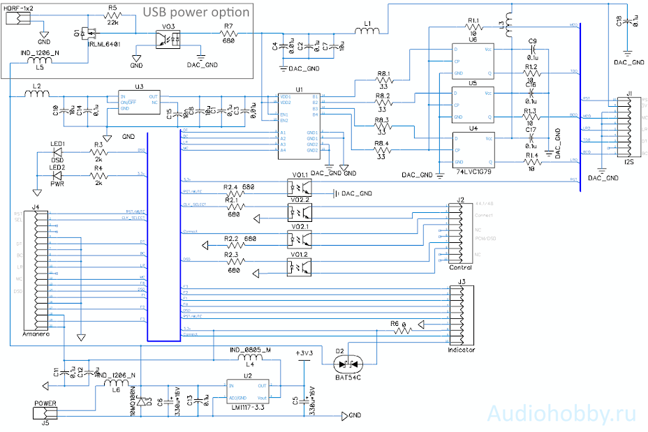
Isolator for Amanero USB I2S with reclock

 Isolator for Amanero USB I2S with reclock


It is recommended to use the board with USB modules  converted to "slave" mode  (receiving a clock signal from the DAC board). 

At the same time, the board allows the use of amanero in master mode, but for this you should use another isolator (for example, ADUM1400CRW), the relevance and expediency of using a reclock in this case is sharply reduced.

Printed circuit board

The device is made on a 42x78mm double-sided printed circuit board. Below is a 3D view of the PCB with components


Adapter circuit with reclock


D-triggers can be replaced with the new AUP series - 74AUP1G79. 

The "USB power option" part of the circuit is unsoldered only if you are going to use power from the USB port. When using this option from the amanero board, just like in the case of external power, remove the standard LDO for 3.3v and apply 5V power from the USB connector to the "USB + 5v" pin. 

The design has been tested over a year with various DACs and has shown good results. The most noticeable results when using reclock were obtained with TI - PCM179x chips. 

For chips from AKM, there is a very small gain in sound  at low sampling rates compared to a conventional adapter without reclocking.    

When using the 22.5792 / 24.576 MHz clock generators used in the Amanero, the maximum sampling rate when using the reclock is capped at 192 kHz. 

Unfortunately, this limitation does not allow us to recommend this board as the main option for the AH-D6x line. 


RKV II Part. 2


PCL805 Tube Headphone Amplifier

RKV mkII

- by Helmut Becker 

I was allowed to publish this report, which was published in the magazine ELRAD 1984, issue 6, with the express kind permission of Mr. Helmut Becker ( www.audiovalve.de) on the Jogis-Röhrenbude homepage. All rights of the author, Mr. Becker, remain unaffected.

All photos and texts shown on this and the associated sub-pages (including extracts), should they be passed on to third parties, require my express consent.

Any commercial use is hereby prohibited.


Most stereo equipment manufacturers pay little attention to the fact that headphones are some of the best transducers.
Almost all amplifiers have a headphone output, but this usually represents a very bad compromise in terms of its technical design.

Plain, bad and simple
Usually the headphones are simply connected in parallel to the loudspeaker terminals, whereby the loudspeaker can be switched off if desired. Since there are headphone systems with an impedance of 8 to 2000 ohms, a resistor of around 300 ohms is placed in the headphone lead, which in 8-ohm systems causes an overload due to excessively high voltage but, on the other hand, does not cause a noticeable voltage drop when connecting high-impedance systems .
So far it works pretty well. Unfortunately, it is too often forgotten that dynamic headphones, like loudspeakers, require damping due to the low internal resistance of the amplifier output. The mentioned series resistance prevents this consequently.
Another shortcoming of this solution lies in the fact that the supply voltage of loudspeaker amplifiers is usually too low. Hi-fi headphones are almost exclusively high-impedance (600-2000 ohms) and need a correspondingly high voltage for control. The power amplifiers designed for low-impedance loudspeaker loads cannot keep up here. The consequence is a separate headphone amplifier.

Effort that is worth it ...
A loudspeaker amplifier with a very low internal resistance should supply a very low-resistance load with relatively low voltages and high currents, a task that is tailored to the transistor.
However, we want to supply a relatively high-resistance load with comparatively high voltages at low currents, although with a low internal resistance. Of course, this also works with transistors. But we remembered a component that the older ones still have fond memories of.

The tube is coming ...
For the catalog of tasks described above, a tube assembly is ideal. High supply voltage is a necessity for tubes, so they can also handle high signal amplitudes. Since the load is high-impedance, you can do without the output transformer that is unavoidable when using loudspeakers. This leads to an ironless tube power amplifier of the highest quality, which is far superior to most transistor amplifiers.

... the transistor stays.
However, we haven't completely banned semiconductors. Wherever tubes have their weak points - they are subject to certain manufacturing tolerances and, as components subject to high thermal loads, they show relatively severe aging - semiconductor components take on the task of controlling and regulating fluctuations in the operating point.
When connecting headphones to the output of a loudspeaker amplifier that has been rated as excellent up to now, one often learns what else arrives apart from music. It rustles, buzzes, crackles and hisses ... and the loudspeaker does not notice any of this.
Naturally, headphones are much more sensitive transducers than loudspeakers. Even the slightest noise and hum tensions are mercilessly brought to the ear. The requirements for a headphone amplifier are correspondingly high.

Can be heard
The circuit shown, which was developed by Helmut Becker and registered for a patent (P 3200 517.2), also shows excellent behavior here. A comparison with the P 3090 from Onkyo quickly revealed that there were no significant differences to the much more expensive reference. Together with the dynamic DT 880 Studio headphones from Beyer, the amplifier reproduced everything that was in the grooves, cleanly and naturally. He brought dynamic passages and solemn passages impeccably. Solo voices and orchestra came with very little coloration.
In brief, the advantages of the circuit concept once again:

  • excellent metrological data (see below)
  • tonally balanced, sharply contoured, powerful sound
  • high dynamics, so CD-compatible
  • high damping factor, lowest internal resistance
  • ironless adaptation to impedances between 30 and 3000 ohms
  • Can be expanded with a preamplifier and thus upgraded to a linear integrated amplifier


The circuit
As can be seen from the circuit diagram (Fig. 1), the two output tubes are connected in series in terms of DC voltage, so that the available supply voltage is distributed over both tubes.


Fig.1

In order to avoid an unnecessarily high operating voltage, tubes would have to be used which still allow strong currents at an anode voltage of around 150 V. Since the range of LF tubes is consistently matched to high anode voltages, the choice fell on a tube type that was standard equipment on television sets around ten years ago.


The triode-pentode PCL 805 meets the above requirements, but has serious disadvantages in other respects, which must be taken into account and eliminated in the rest of the circuit concept. For example, the relatively strong heating hum of this type of tube is effectively suppressed by a control circuit and the strongly curved control grid characteristic is compensated.


The block diagram shown above illustrates the circuit principle, which is based on three functional groups.

  • Reference voltage source as a reference point for all controlled variables
  • Operational amplifier as a control element
  • Tube power amplifier

The tube output stage

The tubes 2 and 3 are connected in series in terms of DC voltage and therefore carry the same current. If it is ensured that an equally large voltage drop occurs on both tubes, the maximum possible modulation is achieved, tube 1b works in anode-base circuit, while tube 2b is used in cathode-base circuit. The negative grid bias of tube 2b defines the operating point of the output stage. It is advisable to choose the operating point for AB operation.
The tubes 1a, 2a serve as driver stages and at the same time ensure the antiphase control of both output tubes. 

If the grid voltage at tube 2b increases, the grid voltage at tube 1b must decrease - and vice versa. In the process, the voltage potential at the connection point A between the tubes 1b and 2b is shifted. The entire arrangement works like an electronic potentiometer, which is placed between ground and supply voltage and whose tap leads to the output electrolytic capacitor C2.


The operational amplifier
The tasks of the operational amplifier are:

  • Check the operating points of the DC coupled amplifier
  • Control of the AF signal to be processed

In order to monitor the operating points of all amplifier stages from one point, a galvanic coupling is necessary. As can be seen from Figure 1, this is the case for the tube systems Rö 1a, 2a, 1b. The operating point of Rö 2b is determined solely by the negative grid bias. A certain internal resistance arises for Rö 2b. The voltage potential that results at point A is divided down with R1 and R2 and compared with the reference voltage URef by the OpAmp. 

The output voltage of the OpAmp will now shift the operating points of the tubes Rö 1a and Rö 1b until the voltages at the inverting and non-inverting input of the OpAmp match. The reference voltage URef at the inverting input of the OpAmp thus determines the voltage potential at point A.


If URef is selected so that half the supply voltage U a is at point A , the two output tubes have the same internal resistance, the same power loss is implemented in both, and the controllability reaches its maximum.


Figure 1 also shows that the reference voltage is superimposed on the LF input voltage. When modulated, the operating points will shift in the rhythm of the input voltage in the sense that a true copy of the input signal is created at the output of the amplifier - but amplified by the resistance ratio of R1 and R2.

The rather complex control circuit gives the circuit some remarkable properties. A problem with tube circuits is the heater hum. The alternating current flowing through the filament of the tube creates a magnetic field which of course also penetrates the cathode and can lead to a 50 Hz modulation of the anode current.


Since such a hum disturbance occurs within the control loop in the circuit concept described, it is largely corrected if only the reference voltage is clean and hum-free. However, this requirement can be met very easily by good sieving and smoothing with a fixed voltage regulator.


Signal-to-noise ratios of 130 dB (A) can be achieved in this way.
Another advantage of the circuit concept is the complete compensation of the characteristic curve curvature of the tubes used. Manufacturing-related tolerances and age-related shifts are automatically compensated. In addition, the regulation, which corresponds to a strong negative feedback in terms of alternating voltage, ensures an extremely low internal resistance of the output.

Power supply unit


Although the amplifier with its mixed equipment requires a large number of different supply voltages, the mains transformer manages with two secondary voltage windings. 

To generate the anode voltage, a winding with 250 V and 100 mA load capacity is sufficient to supply a stereo output stage.


The second winding generates the heating voltage for the tubes: 

The PCL 805 requires 18 V at 300 mA heating current. 

Since two tubes are connected in series, a transformer voltage of 36 V with 0.7 A load capacity should be selected.


The positive and negative supply voltage of the OpAmp as well as the negative grid bias voltage for Rö 2b and the positive reference voltage URef are also derived from this winding.


(Corrected Schematic, see text.)


*****C23 is 220nF/100V is missing in the original schematic!

****Adjust P1 to make a ~3.5Vdc voltage bias on the node of C13 and R13.

Construction

Unfortunately, a double-sided circuit board could not be avoided when developing the circuit. For this reason, self-production is reserved for the experienced etcher.

When equipping, it is advisable to start with the power supply unit. All components that are used for the power supply must be soldered in. 

These include the rectifier Gl1, the diodes and Zener diodes D1-4 and D11, the capacitors C1-14, the resistors R1-5, the trimming potentiometer P1, the fixed voltage regulator IC1 and the two fuses Si 1, 2.

Before you start the Connect the transformer and check the voltages, a word about dealing with high voltages: The anode voltage of the device is over 300 V! 

That is a value that may be enough to send you to the eternal hunting grounds.


Only work on the device when it is switched on if it cannot be avoided and then with extreme caution. Above all, remember that after switching off the device, the voltages on the high-voltage electrolytic capacitors C14, 24, 24 ', 25, 25', 26, 26 'are retained for a long time.

So before you grasp heartily with both hands, even when the device is switched off, you should discharge the capacitors mentioned.

This is done via a 1 k, 4 W resistor, by no means through a short circuit, because an electrolytic capacitor does not like it when it has to supply currents of over 10 A for a short time.

Now switch on the device and check the voltages relative to ground:

at C14 approx. +315 V
at C4 approx. -18 V
at C8 approx. +22 V
at C10 approx. +12 V
at C12 approx. + 6V

The voltage at C13 is initially set to about 3.5 V with the spindle trim potentiometer P1.


If the voltage values ​​are correct, after switching off the device and after discharging the electrolytic capacitor, the next step is to solder in the tube socket and insert the tubes in order to then convince yourself of the function of the heating filaments. 

After switching on the device, the glowing heating wire should be visible at the upper end of the inside of the tube after a few seconds.

After switching off and unloading again, the rest of the equipment begins.

Once all components have been soldered in, the amplifier can be put into operation and adjusted. To do this, the voltage at C26 or C26 'is measured. 

It should initially be between 100 and 250 volts and can now be set to around 160 volts with P1.


If you now short-circuit the LF input and check the output signal with an oscilloscope, nothing should be seen except for a very small noise signal. The same test is carried out on the second channel.


To set the symmetry, a 1 kHz sinusoidal signal is applied to the amplifier input. 

The output is loaded with a 390 Ohm, 4 W resistor and the output signal is monitored with the oscilloscope. 

Now increase the input voltage until the limitation of the output voltage is visible on the screen. By slightly readjusting P1, the operating point is shifted until the limit is the same for a positive and a negative half-wave. 

No distortion of the sinusoid should be visible until shortly before the limitation starts.
If you do not have an oscilloscope available, you can be satisfied with bringing the voltage at C26, C26 'to half the anode voltage.

Technical data (measured on the finished device) :

Output line: 3.4 W at 100 Ohm
RMS at 1 kHz 1% Kges. : 6.6 W at 600 ohms

THD : 0.007% at 100 ohms
1 kHz / 100 mW: 0.004% at 600 ohms

Intermodulation: 0.008 at 100 ohms
600/6000 Hz, 4: 1: 0.005 at 600 ohms

Power bandwidth : 2 Hz - 120 kHz at 100 ohms
-3 dB: 1 Hz - 140 kHz at 600 ohms

Damping factor:> 10 4

Input sensitivity:
0.2 V for 1 watt at 100 ohms
0.5 V for 1 watt at 600 ohms

Input impedance: 100 kOhms (without Volume poti)

Signal-to-noise ratio:
113 dB (A), 50 mW at 600 ohms
138 dB (A), 2 W at 600 ohms

Output voltage: 80 V (RMS)
Rise time (40 V at 600 Ohm): 80 V / uS

Power output: 2 - 3 dyn. Handset (imp. Approx. 400 ohms)

Mains connection value: 220 V / 50 Hz, 40 VA


The circuit board - layouts and assembly


(Layout of the wiring side)

(Click on the respective layout with the mouse button, it will then be displayed in full resolution.) (Layout of the component side)


The parts list for this headphone amplifier:


This amp is still offered today (of course with some improvements in the meantime) at Audiovalve under the name RKV Mark II:


About Tubes: 

ECL85/6GV8-XCL85/9GV8-LCL85/10GV8-PCL85/18GV8 

is a very good tube for audio amplifiers, very linear, with lower internal resistance and 

with lower supply voltages uses an output transformer of lower primary impedance 

(read: cheaper!) 

than the tube ECL86 / 6GW8-PCL86 / 14GW8, which is much cheaper and lighter to procure.

The improved ECL805 / PCL805 variant, which has an increased maximum plate dissipation (especially from TELEFUNKEN) of Pa = 11W, is even better, but it is also increasingly difficult to find.


Due to reliability Problems the PCL85 (Pa= 7W) became the successor PCL805 (Pa= 8W) where nothing else had been changed except the pentode power rating.

For the same reason the pentode part had been put into a single envelope, which was named PL805 then (with "E"-Heater also produced as EL805).

It is very easy to mistake the PCL805 for the PCL86 from the outside - especially if the lettering has become illegible. - So take care!


The following photos show a PCL805 (left, Philips production) and a PCL86 (right), each side by side. - Since both are Valvo-labeled, the slight differences that can be seen (anode sheet, etc.) could be due to internal reasons.

It is therefore quite possible that an ECL805 and an ECL86 from a different manufacturer have slightly different differences, or could even be completely similar!


Audio Valve RKV HPA with PCL805

Tube headphone amplifier with PCL805 08/15/2007

Source Files download


The picture below shows the max Output voltage before soft clipping in OTL mode under 220 Ohm load per channel,  reaching 43 Vrms for 8.3 wattsper channel.


If you are not sure which tube you need, please look at the circuit board and see what is written there (PCL805), or ECL85 (6F5P).

In mid-2015 it has been changed from PCL805 to ECL85 that affects the models of all RKV, Luminare and Solaris.

Description of some technical details ...

The output impedance of Luminare with negative feedback (physical concept: closed loop) is defined as follows.

The control is based on the principle of negative feedback of the open loop gain ( 133 dB ) of the amplifier. 

However, since there is a closed loop. Dynamically because the amplifier tries to keep active voltage at the output losses in upright because he
continuously compares its actual value (feedback) to the desired value (signal) and continuously re-adjusts addition, through the entire range.  

Example: The OTL mode provides Luminare 1V without load resistance and 0.998 V at 60 ohm load resistor.
From these data it can be calculated easily, that the output impedance of the amplifier for this load resistance 0.12 ohm.

The fact of wanting to determine the output impedance by incorporating the tubes, is simply nonsense.

It's not the tube determines the output impedance, but the overall OTL concept.


This applies to RKV 2 + 3 and Luminare. 

The output transformer is not the part of its gain loop.  
If you are interested in the circuit design, read the patent in 1982 below.


Tube Rolling is simply stupid in the models RKV, Luminare and Solaris. You can convince yourself by knocking on the tubes, and you will not hear any knocking sounds in the headphones.


Inside the power inlet a fuse can be found as a protection against overload.
For the 117 V version the value of the fuse should be 1 Ampere Slow.
For the 235 V version the fuse is 0,63 Ampere Slow.


In the end I found what I was looking for at Jogi's tube booth , where there is a circuit with two PCL805s (per channel) in push-pull operation (see under Amplifier - PCL 805-Headphone-Amp). 

The advantages of this circuit:

Very high output power (mei, as a rocker you just need pressure)
Proven design (originally by Helmut Becker)
No output transformer 
Except for the mains transformer and tubes, only standard components


ATTENTION !!

If you want to build and operate this power amplifier, you should know exactly what you are doing. The mains voltage as well as the anode voltage for the output stage tubes (375V) are freely conducted in the device. Improper handling is life-threatening! Even after switching off, you must wait until the electrolytic capacitors are discharged (check with a multimeter) before continuing to work on the device! I am not responsible for any damage caused by the replica!
First construction - we iron a layout!

The schematic was quickly nailed up in Target3001 and turned into a layout. 
But stupid: Just when it was time to create the circuit board, I noticed that I had overestimated the capacity of my circuit board store: There were no photo-positive coated circuit boards in the right size. Damn! However, I still had copper-coated circuit boards WITHOUT photoresist, and it occurred to me that I had once read about the "toner transfer method". 

The layout is printed out with a laser printer and ironed onto the copper of the circuit board with an iron. Then carefully rub the paper with washing-up liquid and the toner covers the tracks that should remain in place during the etching.


Thomas Pfeifer , for example, has more information on this on his website. What can I say: It worked! Even if the edge sharpness is not the very best and I had to repair one or the other membrane afterwards - it wasn't bad at all for the first time.


Power hungry

The first switch-on - still without the anode voltage connected - went well, the heating of the tubes began to glow, all voltages were within tolerance, so after switching off I activated the anode voltage and switched it on again. Not without an ammeter in between - I probably suspected it: As soon as the tubes come up to temperature, the anode current continues to rise ... So quickly switched off the whole moped again. Then something is probably wrong.


The troubleshooting took a lot of nerves, I kept checking the structure, comparing it with the circuit diagram ... nothing! 

Everything as it should be.
After another week I was on the verge of giving up the project, but as a last, desperate step I looked at the original layout on Jogi's side and reproduced it with the circuit diagram - 

HUPS, there is a capacitor where there is none in the circuit diagram! 

Yes, of course, without it the lower tube is at the wrong working point in terms of DC voltage and is fully open! 

You could have seen that on the circuit diagram, but sometimes you can't see the forest for the trees ...

Here is the original scheme from Jogi's site with my correction:


Lo and behold, as soon as the capacitor was installed, the circuit ran, the anode current remained within its limit. To be on the safe side, one last test, signal generator to the input, 330 ohm load resistor and oscillator to the output, and see what the amp does. 

In principle it looks good, the signal comes out nicely amplified, but there is a clear hum. This is confirmed by the hearing test with MP3 player and headphones - it works, but it buzzes like a bag of bumblebees ...
Growl

So what to do


We wanted a two-sided layout, with a thick ground plane on one side. Because my guess was that it is a pure mass problem. In addition, the heating cables should be completely removed from the circuit board and wired freely in order to avoid voltage drops across the ground. 

The implementation of the layout was not so easy, however: I had to have a two-sided board made, the self-etching was too tricky for me, because the board is quite large and so the congruence of the two layers is difficult. 

Since it was the PCBPool Edition, I could only use Target3001 in conjunction with the PCBPool , and the guys are not cheap ...

So I decided to try KiCAD , a free CAD program for circuit board development published under the GPL license. 

Circuit board size practically unlimited, lots of free libraries from other users, that sounds really good, doesn't it?


KiCAD

To anticipate: it took me some time to get used to the KiCAD version of that time (from 2005) ... First the usual training hurdles until one understood the philosophy of the program, and then there was also the one or other bug that made life difficult for you. 

Fortunately, a lot has happened in the meantime, and today I only use KiCAD in my private life. You have no restrictions with regard to the number of pins, etc., you can generate Gerber files directly and are therefore not tied to a circuit board manufacturer.

Back to the topic - somehow I got the circuit board strapped and after three weeks of waiting it was in my mailbox. I ordered them from LeitOn , which made a good impression and, according to the online calculator , had one of the cheapest prices.

Lo and behold, after "moving" the components from the old circuit board to the new one and running through the commissioning tests again, the first hearing test followed, and the humming was significantly reduced, but unfortunately still not completely gone ...
The breakthrough

The real breakthrough came with a tip from Helmut Weigl , who - independently of me - also shared a replica of the amplifier and also stumbled upon the problem with the missing capacitors. 

I helped him with the capacitors, and in return he gave me tips on how to reduce the hum. If that is no help among hobbyists - Thank you, Helmut!


The grounding at the inputs of the two operational amplifiers is very important. 

There should be a central ground point for each channel, to which the voltage divider from the audio input as well as from the feedback and the headphone output refer. Without further ado I created this grounding by scraping open the grounding lines from the potentiometer and connecting them directly to the OpAmps with wire. 

Lo and behold, your colleague is no longer grumbling! Bingo!!


Layout, the third ...

In October 2012 I implemented the previous knowledge in a new layout so that you can easily and successfully recreate the amplifier. 

There the grounding has been changed again, it is a two-sided layout WITHOUT a ground plane, so that you can theoretically build the amp on a one-sided circuit board if you then lay the missing connections with wire. 

In addition, I brought in some of Helmut's ideas and changed the power supply again so that the operating voltages are cleaner (without ripple voltages) (with the exception of the 350V, where a small ripple voltage has no influence on the hum at the output). 

Furthermore, a new volume potentiometer from ALPS has been added, which has a better synchronization and hopefully lasts longer - the cheap potentiometer from the old amplifier was already starting to scratch ...

I ordered this board from PCB-Joker , where you can get it for 60 €. The gag with this company is that you don't know what you are getting - it can be a printed circuit board between 0.5mm and 2.0mm thick, with any colored solder mask. While the color is not an issue, I was unlucky with the thickness - I got a 0.5 of all things. For this reason I had to attach an additional fastening in the middle of the board, with a normal 1.5mm board this is not necessary.

The complete documents on the RKV can be downloaded here. 

The archive contains:
KiCAD project
Gerber
BOM
Front panel files for the housing
(can be ordered directly from Schaeffer ).


setup and start-up


After setting up the amplifier and checking the equipment (the tubes are not yet fitted!) 
You should first connect only the 36V winding of the transformer and switch on the amplifier. 

Then you should check the following points:
+ 22V via D20 (22V-Zener-diode)
+ 12V at C44 (output of the 12V regulator)
-8.2V via D19 (8.2V Z-Diode)
-18V via D21 (18V-Z-Diode)

If all voltages are OK, you set a voltage to approx. 3.5V with the potentiometer RV2 via C4, the same with RV3 3.5V via C17.

Now you can switch off the amp again and connect the high voltage from the transformer. 

ATTENTION, from now on it will be dangerous !! After switching on you should measure a voltage of approx. 375V via C36 (this voltage is even higher than later in operation, since no tubes are plugged in yet and therefore no anode current is flowing). 

If this voltage is also fine, you can switch off the amp.

IMPORTANT: wait until the C36 is discharged to a safe voltage and then insert the tubes.

If you turn on the amp now, the tubes should heat up. During the heat-up time, a strong fluctuation in the output voltage can be seen at the headphone output, which should calm down after the end of the heat-up time. 

To properly balance the amp, a function generator (1kHz, sine) is connected to the input, a load resistor (300 to 400 ohms, 5 watts) plus an oscilloscope connected to the output. 

Now the amplitude of the generator is slowly increased (don't forget the volume potentiometer) until the signal at the output begins to distort and the peaks of the sinusoidal signal are cut off. 

The amplifier is then set with the potentiometer of the respective channel so that the distortion is symmetrical, ie positive and negative half-waves of the sine are cut off evenly. The other channel is set in the same way.

If you don't have an oscillator / function generator, you can simply set the potentiometer so that about 150V is applied to the output electrolytic capacitor (C13 / C26). Then you should be roughly in the middle of the dynamic range.


A few more tips ...

Here are some more information and tips on how to recreate it. The ZIP archive contains a parts list that should contain pretty much everything you need for a replica. Sources of supply and current prices are also given there. Do not be put off by the price, it really includes ALL parts including custom-made transformer, circuit board and housing, and some things are only available in larger quantities (screws, etc.). So you can definitely still save here.

When making a replica, you should make sure that the entire audio signal chain, if at all, should only be grounded at one point (connected to the protective conductor). The housing is designed so that this ground point is at the headphone jack; the cinch sockets, on the other hand, are isolated from the housing. 

If the rest of the audio system is grounded somewhere, you can quickly catch ground loops; then you should look where the ground loop is and break it open.

The metal axis of the potentiometer should also be grounded if possible, otherwise it could crack when you touch the (metal) potentiometer in the headphones.

Don't be surprised if you put on the headphones and turn on the amplifier; at the beginning during the first 10-20 seconds you can hear an illustrious humming concert until the tubes have reached their operating temperature. 

Afterwards, the amplifier should be quiet - at least as far as the hum is concerned ...

************************************************

And now of course the all-important question:
How does it sound now?

I would like to say! Together with my Sennheiser HD570, a really strong duo. Nice sound, well-developed bass, that's how it has to be. And it really is the case that with familiar songs you keep hearing small details that you haven't noticed before. So the construction was definitely worth it for me.
Pictures of the construction

Here are a few more photos of the structure and inner workings of the RKV:


Front view ...


... and from behind.


Interior view of the RKV.


The circuit board in detail. 
In the middle the additional fastening necessary for the 0.5mm board.
Pictures of replicas

************************************
March 2017: 

Uli recreated the amplifier with the original layout of Jogi's tube booth, and came to my site because of the hum problem. Obviously the original is not completely hum-free either, but together we were able to calm the amplifier down a bit. Also a very nice replica!


*********************************

January 2014: 

Stefan cloned the headphone amplifier with his own layout and also added a circuit for volume control via a motor potentiometer, which can be remotely controlled using an infrared remote control. The case is self-built. A really nice piece! 

The complete documentation on this replica can you download here. 

Many thanks to Stefan for providing!


***********************************


March 2013: 

Thomas used the current, the third version of KiCAD layout. 

He made the circuit board himself by simply producing the front and back sides separately on two single-sided circuit boards and then putting them back to back. 

The housing is made of laminated wood with bamboo fittings, the front and back panels are made of 3mm MDF panels painted gray. Became very beautiful!


Note: 

The pictures show a Euro plug without a protective conductor. Due to the metal surfaces that can be touched and the high voltages carried in the device, 

I strongly advise you to use the amplifier WITH a protective contact: 
SAFETY FIRST!

In addition, the cable should be led through a rubber grommet etc. at the housing entrance and provided with a strain relief, otherwise the cable could chafe through and the conductors could come into contact with the housing.


*******************************************************
END OF Mario.de
*******************************************************


E-mu 0404 1212m 1616m 1820m PCI 音效卡 Windows11 驅動程式安裝 2025

E-mu 0404 1212m 1616m 1820m 音訊卡 驅動相容性與安裝 E-mu 0404 1212m 1820m等是歷久彌新的老音效卡,這些是Windows 7 時代製造且相對較老舊的音效卡。當時,AKM旭化成和 Burr-Brown 等廠商的 AD 轉換器都在爭奪板...