TASCAM UH-7000
Professional USB Audio Interface / Standalone Mic Preamp
The TASCAM UH-7000 is a very interesting device for creating high quality recordings. At the higher end price bracket, we usually see the emphasis of manufacturers on the number of I / O, flexible configuration options, expandability, and the like. But the most massive user request turns out to be unclaimed: give the highest quality two channels, with preamplifiers of the highest category, for the most demanding recordings or for studio overdubbing. The same goes for on-site recording with a laptop. It is unwise to move a rack ADC and an expensive tube microphone preamplifier, because of the risk of damaging expensive equipment. Cheap interfaces fail either in terms of usability or sound quality. The equipment is too divided into studio and mass production. There are very few average options - in fact, none.
Specifications TASCAM UH-7000
Conversion characteristics |
| Dynamic ADC range | 123 dBA |
| DAC dynamic range | 123 dBA |
| Frequency response of microphone preamplifiers | 20 Hz - 80 kHz + 0.005 / -0.16 dB |
| Signal-to-Noise Mic Preamps before ADC | 117 dBA |
| Distortion of mic preamps before ADC | 0.0009% |
| A | -128dBu |
| Inputs |
| Linear 1/2 | |
| Connector | TRS, balanced |
| Maximum | +26.5dBu |
| Minimum | --38dBu |
| Impedance | 15 kΩ |
| Microphone 1/2 | |
| Connector | XLR, balanced |
| Maximum | +2dBu |
| Minimum | -60dBu |
| Impedance | 2.2 k Ohm |
| Outputs |
| Linear 1/2 | |
| Connector | XLR, balanced |
| Maximum | +24dBu |
| Impedance | 100 ohm |
| Headphone | |
| Connector | 1/4" TRS |
| Power | > 45mW + 45mW (Kg + noise <1% at 32 ohm) |
| Digital interfaces |
| AES/EBU | |
| Connector | XLR input, XLR output |
| Format | S/PDIF, AES/EBU |
| Frequencies | 44.1 / 48 / 88.2 / 96 / 176.4 / 192 kHz |
| USB |
| Connector | USB A-type |
| Protocol | USB 2.0 |
| Nutrition |
| Mains voltage | 100-240V, 50 / 60Hz |
| Consumption | 15W |
| Dimensions (edit) | 214 (W) × 81.2 (H) × 233 (D) mm |
| The weight | 2.2 kg |
In the category up to $ 600, the E-MU1616M card was undoubtedly popular among the decent digitizers. But it does not have a USB connection, is inconvenient in operation, and, at the moment, has completely gone out of sales. In a hurry to please our readers, the TASCAM UH-7000 is an absolutely healthy alternative to the E-MU1616M, as well as any other professional interface in this category. Among USB interfaces, MOTU Track16, RME Babyface, Apogee Duet immediately come to mind ... This is at its best!
But, compared to the TASCAM UH-7000, these are, nevertheless, budget sound cards for a laptop.... Their invariable attributes: power from the USB bus or from a rootless Chinese pulse power supply unit, an obscene input for a guitar, a weak headphone amplifier, and 16-20 more connectors on a pigtail, on a Chinese 40-pin connector. This is done with the best intentions, supposedly suitable for anything, and it costs a lot. However, in practice, professionals are not very interested in such devices, their main audience is amateurs, with claims to ...
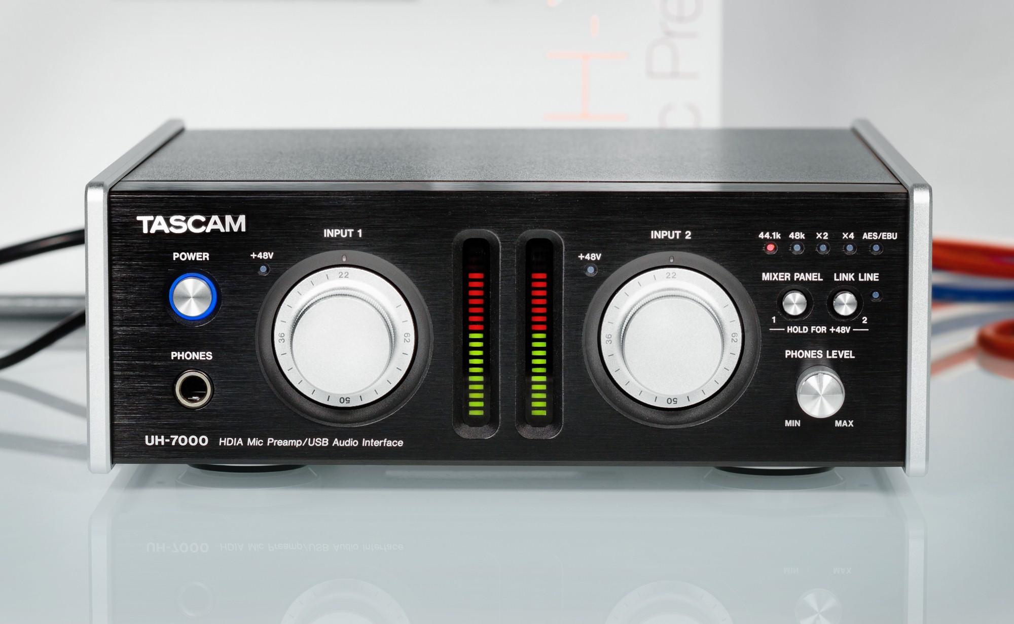
The absolutely all-metal TASCAM UH-7000 case, quite heavy, with its internal weighty power supply unit from 220 Volts, with full-fledged balanced Neutrik input and output connectors, contrasts sharply with the products of mass culture. Moreover, line and microphone jacks are separated, no XLR / TRS combo. Microphone Amplifiers - High Definition Instrumentation Architecture. The brand name does not bring clarity, it is much more important that this is the newest development of TASCAM, for recording in high DSD and PCM formats. For stand-alone operation (that is, without a computer at all), the TASCAM UH-7000 is officially recommended by the manufacturer as a Hi-End microphone preamplifier for the TASCAM DA-3000 rack-mount DSD / PCM recorder.
And that's why. Let's tell you right away that the sound on the recording is different from the usual inexpensive mic preamps. Something of its own is present in the sound, a certain signature handwriting. The Neumann TLM sounded even more noble in the midrange than before. And this is without any processing. According to the passport, the microphone preamplifier has a distortion of less than 0.0009%. Therefore, this effect is definitely not caused by saturation or something else, but the correct transmission of the timbre and dynamics of the sound. There was a feeling that the voice on the recording became more beautiful. Explosive consonants and sibilants, even at high amplitudes, do not overload the analogue tract and therefore are then removed by processing without artifacts. The recording is very natural and natural, does not require additional creative searches with a huge chain of intricate plugins.
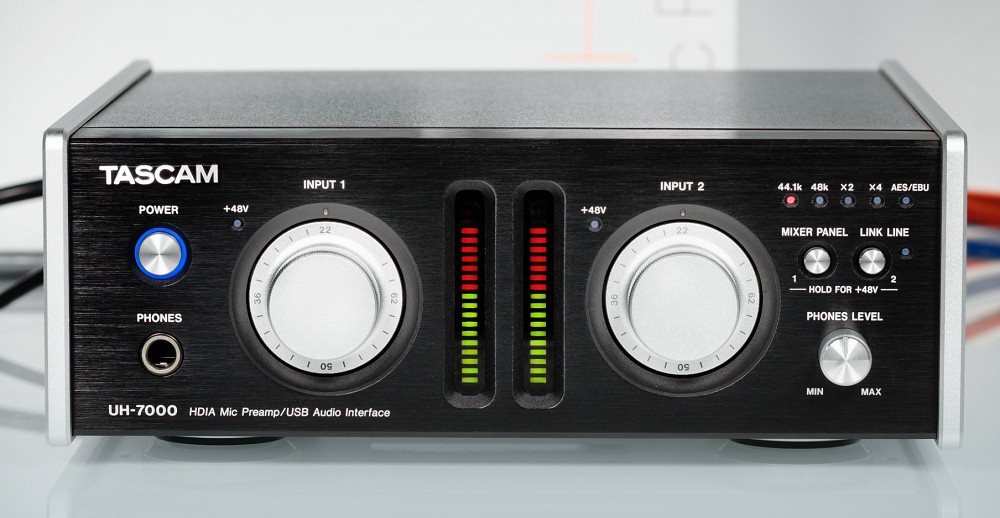
The large front panel level controls and meters are input only. After the tiny twists of inexpensive audio devices, working with such controls is the height of delight. In addition to more precise adjustment with a large knob, it is worth noting a well-thought-out logarithmic adjustment scale and a significant gain margin. LED multi-segment picmeters in this price category are not found at all.
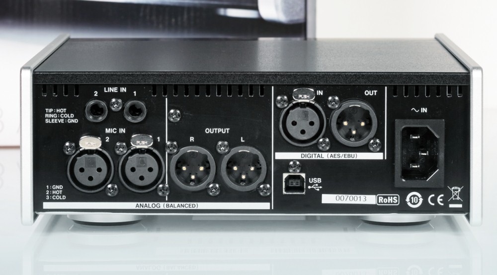
The voltage margin of the inputs and outputs is very high, which without any problems gives the pairing with studio rack ADC / DAC, where +20 dBu is the norm.
In all aspects, the overall impression is very positive. The TASCAM UH-7000 is a device you can't help but want to have in your arsenal. We especially note the high-quality headphone output and the overall high quality of the converters. A good DAC is immediately audible in headphones and monitors. According to the passport, 123 dBA is declared. This is not as important as really good sound when the difference is heard. The numbers are just numbers.

Here we noted the thermostabilized oscillators with a stability of +/− 1ppm.
ADC Burr-Brown PCM4220.
DAC Burr-Brown PCM1795.
Proprietary microphone preamps are assembled on the TI OPA 1612A, with the highest characteristics: noise 1.1 nV / √Hz, distortion 0.000015%, slew rate 27 V / μs, bandwidth 40 MHz.
TI NE5532A is used for line inputs and outputs. The choice of these op amps is unusual, unless we remember their ability to operate with supply voltages up to 30 V and at the same time be resistant to short circuits at the output.
If you are more interested solely in listening, the inputs are not needed, but the capacitors must certainly be Nichicon Gold, it makes sense to look towards DSD DACs such as TEAC UD-501, of the same manufacturer. There will be MUSES op-amps, audiophile gold-plated RCA connectors, and a more powerful headphone amplifier.
The major distortion is caused by the LINE input, where is the weakest circuitry of the device. In addition, the line input is dependent, it is regulated in level from the front panel within wide limits.
RightMark Audio Analyzer Test Report
| Device under test | [ASIO] UH-7000 |
| Working hours | 24-bit, 44 kHz |
| Sound interface | ASIO |
| Signal route | External loopback (line-out - line-in) |
| RMAA version | 6.4.1 PRO |
| | |
| | |
| Filter 20 Hz - 20 kHz | YES |
| Signal normalization | YES |
| Level change | -1.1 dB / -1.2 dB |
| MONO mode | NO |
| Calibration signal frequency, Hz | 1000 |
| Polarity | correct / correct |
Overall results
| Frequency response (in the range 40 Hz - 15 kHz), dB | +0.01, -0.16 | Very good |
| Noise level, dB (A) | -115.8 | Fine |
| Dynamic range, dB (A) | 115.6 | Fine |
| Harmonic distortion,% | 0.0023 | Fine |
| Harmonic distortion + noise, dB (A) | -90.2 | Very good |
| Intermodulation distortion + noise,% | 0.0027 | Fine |
| Interpenetration of channels, dB | -115.1 | Fine |
| Intermodulation at 10 kHz,% | 0.0056 | Fine |
| Overall score | | Fine |
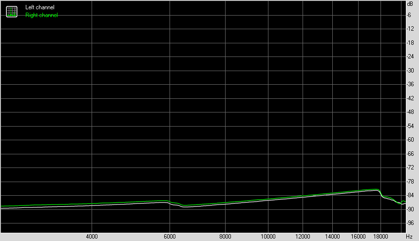
Frequency response
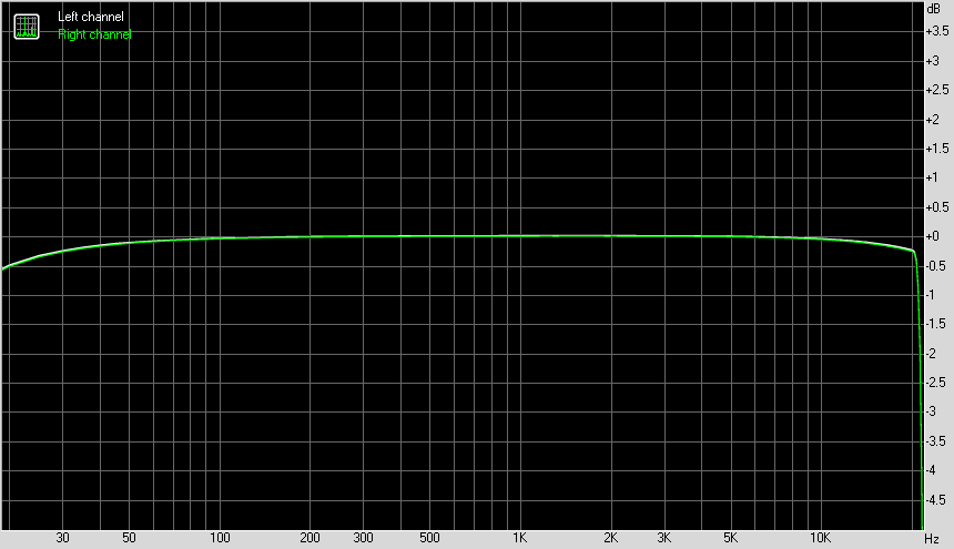
| | Left | Right |
| 20 Hz to 20 kHz, dB | -0.48, +0.02 | -0.50, +0.01 |
| 40 Hz to 15 kHz, dB | -0.14, +0.02 | -0.16, +0.01 |
Noise level
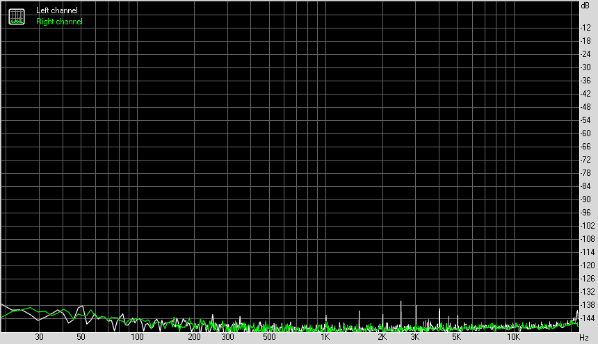
| | Left | Right |
| RMS power, dB | -114.6 | -114.7 |
| RMS power, dB (A) | -115.7 | -115.9 |
| Peak level, dB | -99.8 | -91.9 |
| DC offset,% | +0.0 | +0.0 |
Dynamic range
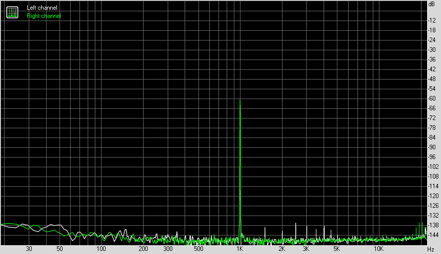
| | Left | Right |
| Dynamic range, dB | +114.4 | +114.5 |
| Dynamic range, dB (A) | +115.5 | +115.7 |
| DC offset,% | +0.00 | +0.00 |
Harmonic distortion + noise (-3dB)
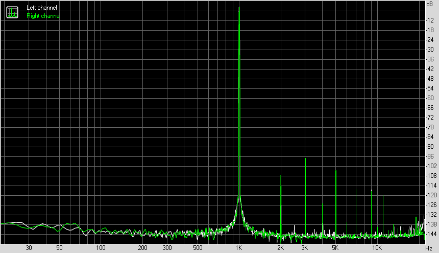
| | Left | Right |
| Harmonic distortion,% | +0.0022 | +0.0024 |
| Harmonic distortion + noise,% | +0.0023 | +0.0025 |
| Harmonic distortion + noise (A-weighted),% | +0.0030 | +0.0032 |
Intermodulation distortion
| | Left | Right |
| Intermodulation distortion + noise,% | +0.0025 | +0.0028 |
| Intermodulation distortion + noise (A-weighted),% | +0.0018 | +0.0020 |
Interpenetration of stereo channels
| | Left | Right |
| Penetration at 100 Hz, dB | -113 | -110 |
| Penetration at 1000 Hz, dB | -114 | -114 |
| Penetration at 10,000 Hz, dB | -113 | -112 |
Intermodulation Distortion (Variable Frequency)
| | Left | Right |
| Intermodulation distortion + noise at 5000 Hz, | 0.0042 | 0.0046 |
| Intermodulation distortion + noise at 10,000 Hz, | 0.0049 | 0.0053 |
| Intermodulation distortion + noise at 15000 Hz, | 0.0071 | 0.0076 |
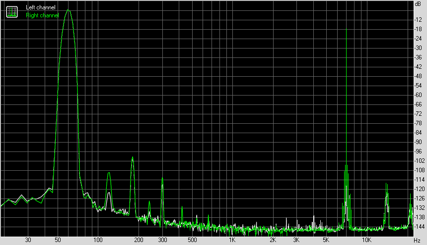
Measurements of the TASCAM line-out to the Lynx Aurora 8 line-in in 24-bit 44 kHz mode are on a separate page.
In summary, the THD of both devices do not exceed 0.0005%.
The measurements were performed on a desktop computer without any optimizations. As we can see, there are ABSOLUTELY no problems with noise and interference. Generally, it is their own PSU that makes the differences.
ASIO diagnostics
Device: UH-7000
Features:
Input channels: 4
Output channels: 4
Input latency: 524
Output latency: 710
Min buffer size: 256
Max buffer size: 256
Preferred buffer size: 256
Granularity: 0
ASIOOutputReady - not supported
Sample rate:
8000 Hz - not supported
11025 Hz - not supported
16000 Hz - not supported
22050 Hz - not supported
32000 Hz - not supported
44100 Hz - supported
48000 Hz - supported
88200 Hz - supported
96000 Hz - supported
176400 Hz - supported
192000 Hz - supported
352800 Hz - not supported
384000 Hz - not supported
Input channels:
channel: 0 (Analog 1) - Int32LSB
channel: 1 (Analog 2) - Int32LSB
channel: 2 (Digital 1) - Int32LSB
channel: 3 (Digital 2) - Int32LSB
Output channels:
channel: 0 (Computer 1) - Int32LSB
channel: 1 (Computer 2) - Int32LSB
channel: 2 (Computer 3) - Int32LSB
channel: 3 (Computer 4) - Int32LSB
4 channels of the device allow flexible use of digital I / O as additional I / O or for connecting external processing.

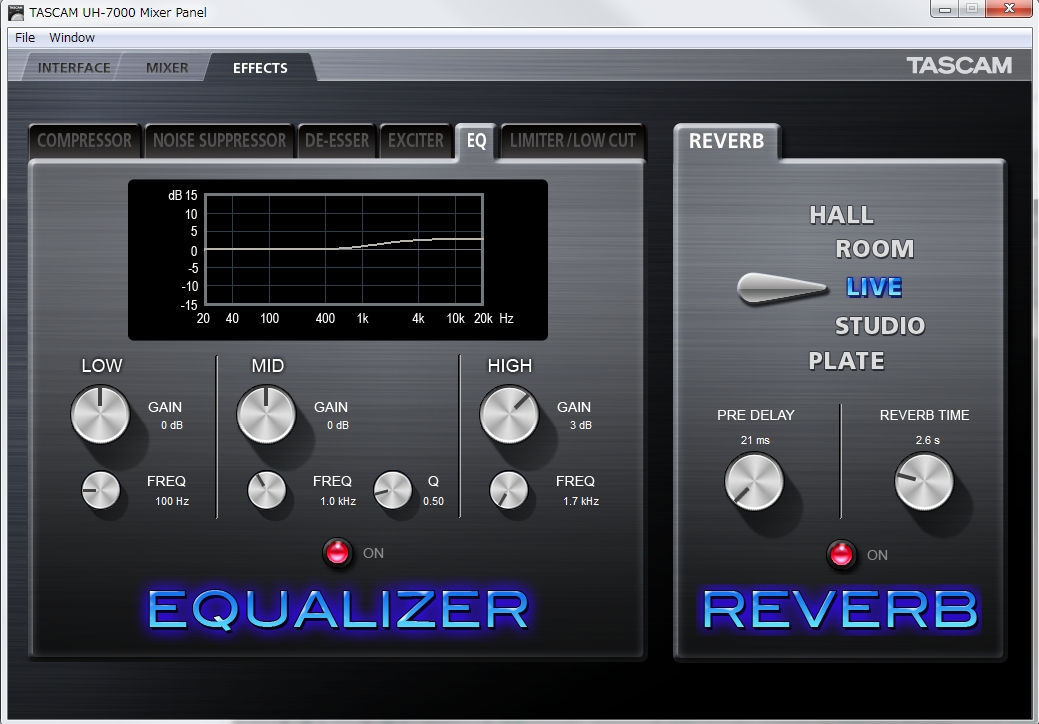
The signal processing, is based on hardware or say, DSP, can be configured by control panel.
It is clear that now there is little sense in a hardware DSP for studio purposes. One of the applicable options - you can monitor the processed signal in headphones while recording, and select to listen unprocessed sound.
Or, for example, you can equalize your headphones by increasing gain of high or low frequencies. Useful applications can be found.
We found out that TASCAM UH-7000 is not a sound card, it is not a digitization interface. First of all, it is a high quality microphone preamplifier for well-known brands of high category microphones.
Further, it is a very high-end DAC and a good headphone output. The TRS line input and hardware DSP are made more "for show", but since no one forces you to use them, this does not spoil the impression.
We have found the following application for the line input - if you apply an output signal to it, then the output signal will be effectively displayed on the picmeter in front of the device, which is impossible to reach by standard means. At the same time, the sound can be monitored from the headphone output.
The sound quality of the TASCAM UH-7000 impressed us. The genius of TASCAM engineers was revealed here in all its glory. Potentially a hit. More devices of such a high level would be produced!