

© Brooke Clarke 2007
Background
Since a crystal oscillator has a temperature dependence you get better performance when the crystal and the associated oscillator are enclosed in an oven. A measure of how good the oven is performing is how much the inside changes temperature when the ambient temperature changes one degree. By using double ovens and maximizing the gain of the temperature control loops the level of oven performaqnce is improved.
These were used in the HP Z3815A which was a GPS disciplined oscillator used for cell phone timing (maybe in Australia).
These were used in the HP Z3815A which was a GPS disciplined oscillator used for cell phone timing (maybe in Australia).
Major ICs
U105
44pin Microcontroller (PIC)
marked E1938-80002, Rev 3719, 9729B
(Fig 1 upper right)
U104, U105
U104, U105
16 pin
AD7243 CMOS, 12-Bit Serial DACPORT - 100k S/s
(Fig 1 just to the left of U105)
U11
U11
28 pin CMOS, 3V/5V, 24-Bit Sigma-Delta, Signal Conditioning ADC
(Fig 1 bottom center)
U200
U200
14 pin
LMC660 CMOS Quad Operational Amplifier (Fig 1 upper left)
Versions
There were different versions:
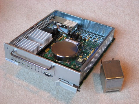
The Z3815A GPS Time Frequency Reference GPSR-A VXI instrument like this one has a D connector on the bottom with sockets.
The E1938A puck on PCB as shown above (has a D connector on the top with pins.)
E1938-60201 is just the puck
The Z3815A GPS Time Frequency Reference GPSR-A VXI instrument like this one has a D connector on the bottom with sockets.
The E1938A puck on PCB as shown above (has a D connector on the top with pins.)
E1938-60201 is just the puck


Operation
Connector

The connector on the bottom of my unit is a special "D" type with 20 sockets and a center hole where a coax connector might be installed (not in this one).
Tom's E1938 has the connector installed on top of the board and his has male pins.
Pin numbers are as shown in the photo on the left.
These connectors will mate with standard DB-25 series connectors, but the pin numbers are only the same for pins 1 to 5. Three pins are skipped between 5 and 6 and two pins are skipped between 15 and 16.
The E1938A was sold to at least 3 major customers and we played games with the connector to make it compatible with them. I don't remember exactly why that funny connector was used. Either the connector it had to mate with had coax inserts already for historical reasons, and the E1938A connector had to at least have holes in it without inserts to allow mating, or there was some other arcane reason like the connector with inserts was a different height or something. Some versions had the connector on the other side of the board. Whatever the reason was, you don't need to worry about it because no version of the E1938A ever used those coaxial positions. I think you can put a regular connector in there if you clip off the unused pins. I vaguely remember shenanigans like that.
-Rick-
-Rick-
Top and Bottom photos annotated with function of each pad or pin. E1938A_Pinout_Pictorial.pdf

Figure 1. Component side of E1938A controller board.

Figure 2. D-sub with coax insert on circuit side of PCB.
Theory of Operation
Theory.pdf explains the schematic and block diagrams.
Back Side Component Locator E1938asdrawa.pdf E1938asdrawb.pdf
Top Side Component Locator E1938asdrawa-8.pdf
GIF format schematics of the board and oscillator and layout drawings as E1938gifs.zip file.
pdf format schematic of the board and oscillator & layout drawings as E1938pdfdocs.zip
On the computerized data printout there is an item called
I am extremely happy with the PII^2D control loop on the E1938A (I didn't design it, only tested it). I can't imagine anything being better.
Top Side Component Locator E1938asdrawa-8.pdf
GIF format schematics of the board and oscillator and layout drawings as E1938gifs.zip file.
pdf format schematic of the board and oscillator & layout drawings as E1938pdfdocs.zip
On the computerized data printout there is an item called
Hz off freq. after warm up:
This is a measure of how well the reasonating capacitor was selected by the factory to center 10 MHz in the EFC window.
Temperature Control
The 10811 has an ANALOG oven control loop. The gain is set to be just below the oscillation point. This is due to the stability limits dictated by the oven mass and (believe it or not) the size of integrator capacitor that can physically fit. If you want to "soup up" at 10811 oven, externally wire a larger capacitor in parallel and change the resistors to increase the gain. The 10811 designers did the best they could with what they had to work with, but you don't want to blindly copy them in new applications. BTW, do not use a "metalized" plastic integrator capacitor. Must be "foil" type.I am extremely happy with the PII^2D control loop on the E1938A (I didn't design it, only tested it). I can't imagine anything being better.
I would like to point out that the E1938A uses a PID controller and has a *transient* thermal gain of many 1000's not to mention a static gain that has in some cases exceeded 1,000,000 for a single oven.
(referring to another temperature control system) The block cannot be well insulated because of the thermal overhead of the oven circuitry (the heat has to escape). I explained in my 1997 FCS paper how to achieve the isothermal condition, which is achieved by symmetry rather than high amounts of insulation. The E1938A oven works quite well if the insulation is omitted or replaced by poor insulation, except that it consumes more power.
Referring to vacuum oven: http://rfdesign.com/vlf_to_uhf/time_and_frequency/709RFDF1.pdf
At HP, in the 90's, we did a lot of brainstorming about vacuum ovens. This never seemed to make sense to us. If you actually achieve high amounts of thermal resistance, then you can't get the heat out of the oven. And if you don't, why bother with a vacuum. Also, a vacuum only helps if you do everything else you need to do to make a true Dewar (thermos bottle), like having mirrored surfaces, etc. Finally, having a vacuum means that nothing that outgasses can be used in the oscillator. Maybe Vectron has figured out something we didn't think of or has sufficiently difference constraints that a vacuum makes sense for them.
We went through this tradeoff on the E1938A. Resistive heaters can be distributed. However, it is very inefficient to drive them with transistors, because then you waste a lot of power heating the transistors, which is waste heat if resistive heating is used. Prior to the 10544, they just put up with this. The 10544 used a switching regulator for up the efficiency, but it put a 1 kHz spur on the oscillator. The 10811 used two transistors on opposite sides to try to sort of distribute the heat. On the E1938A, we looked at an array of small surface mount transistors to have the best of both worlds. However, this turned out not to be manufacturable and we settled for resistive heaters (back to 1970!).
-Rick-
(referring to another temperature control system) The block cannot be well insulated because of the thermal overhead of the oven circuitry (the heat has to escape). I explained in my 1997 FCS paper how to achieve the isothermal condition, which is achieved by symmetry rather than high amounts of insulation. The E1938A oven works quite well if the insulation is omitted or replaced by poor insulation, except that it consumes more power.
Referring to vacuum oven: http://rfdesign.com/vlf_to_uhf/time_and_frequency/709RFDF1.pdf
At HP, in the 90's, we did a lot of brainstorming about vacuum ovens. This never seemed to make sense to us. If you actually achieve high amounts of thermal resistance, then you can't get the heat out of the oven. And if you don't, why bother with a vacuum. Also, a vacuum only helps if you do everything else you need to do to make a true Dewar (thermos bottle), like having mirrored surfaces, etc. Finally, having a vacuum means that nothing that outgasses can be used in the oscillator. Maybe Vectron has figured out something we didn't think of or has sufficiently difference constraints that a vacuum makes sense for them.
We went through this tradeoff on the E1938A. Resistive heaters can be distributed. However, it is very inefficient to drive them with transistors, because then you waste a lot of power heating the transistors, which is waste heat if resistive heating is used. Prior to the 10544, they just put up with this. The 10544 used a switching regulator for up the efficiency, but it put a 1 kHz spur on the oscillator. The 10811 used two transistors on opposite sides to try to sort of distribute the heat. On the E1938A, we looked at an array of small surface mount transistors to have the best of both worlds. However, this turned out not to be manufacturable and we settled for resistive heaters (back to 1970!).
-Rick-
Computer Program
NGOcomm.zip - Windows control program & 3 DLLs it needs.
Papers
A New Type of Balanced-Bridge Controlled Oscillator, R.K. Karlquist, HP Labs, date?, publication?
The Theory Of Zero Gradient Crystal Ovens, R.K. Karlquist, L.S. Cutler, E.M. Ingman, J.L. Johnson, T. Parisek, HP & HP Labs, date?, publication?
A Low-Profile High-Performance Crystal Oscillator For Timekeeping Applications, R.K. Karlquist, L.S. Cutler, E.M. Ingman, J.L. Johnson, T. Parisek, HP & HP Labs, date?, publication?
The Theory Of Zero Gradient Crystal Ovens, R.K. Karlquist, L.S. Cutler, E.M. Ingman, J.L. Johnson, T. Parisek, HP & HP Labs, date?, publication?
A Low-Profile High-Performance Crystal Oscillator For Timekeeping Applications, R.K. Karlquist, L.S. Cutler, E.M. Ingman, J.L. Johnson, T. Parisek, HP & HP Labs, date?, publication?
Patents
Directly Related to the E1938
2004613 Phase Shifting Apparatus, Larned A. Meacham, assigned to Bell Telephone Labs, filed Aug 23, 1933, issued Jun 11,1935, 323/218 ; 361/299.1
2163403 Stabilized Oscillator, Larned A. Meacham, assigned to Bell Telephone Labs, filed July 2, 1937, issued June 20, 1939., 331/139 ; 331/140; 331/183; 331/66; 333/17.1; 333/188 - uses light bulb to stabilize a crystal oscillator.
2268872 Variable Frequency Oscillation Generator, William R. Hewlett, assigned to H-P, , filed June 11, 1939, issued Jan 6, 1942, 331/141 ; 331/183 - this is the model 200A audio oscillator that got H-P started. - uses light bulb to stablize a bridge audio frequency oscillator. The frequency is controlled by an air variable capacitor which would not have any effect on conventional audio frequency oscillators.
2163403 Stabilized Oscillator, Larned A. Meacham, assigned to Bell Telephone Labs, filed July 2, 1937, issued June 20, 1939., 331/139 ; 331/140; 331/183; 331/66; 333/17.1; 333/188 - uses light bulb to stabilize a crystal oscillator.
2268872 Variable Frequency Oscillation Generator, William R. Hewlett, assigned to H-P, , filed June 11, 1939, issued Jan 6, 1942, 331/141 ; 331/183 - this is the model 200A audio oscillator that got H-P started. - uses light bulb to stablize a bridge audio frequency oscillator. The frequency is controlled by an air variable capacitor which would not have any effect on conventional audio frequency oscillators.
The E1938A project started out as a Meacham bridge oscillator and the number was chosen because it was the date of invention of that oscillator. Eventually, we realized that design wasn't going to work for us and we had to invent our our bridge oscillator.
The lamp thing is interesting because there is a lot of HP folklore that has grown up around the HP garage, the invention of the 200A oscillator, etc, and it seems that Bill Hewlett has gotten credit for the lamp stabilization idea. Possibly, he independently invented it, since he filed 6 months after Meacham did, but long before the Meacham patent was granted. Hewlett also copied or reinvented the idea of a bridge oscillator. His real contribution was to harness Meacham's previous technology to enable him to eliminate the inductor from the oscillator, which allowed him to raise the impedance level high enough to allow air variable capacitors to be used. It was a great design, whoever invented it.
(According to tradition, the model number 200 was used instead of 100 to give the impression that this wasn't the first HP product).
The original Hewlett patent is on display at Agilent headquarters where I work. I was kind of surprised that HP ("HP Invent") let Agilent have it. I am also pleased that in the HP Archives museum, on the first shelf, in the center, is a *working* 5071A. There is also, of course, a 200A oscillator on display.
The above are my own opinions and don't represent Agilent or HP.
Rick Karlquist
2275452 Stablized Vacuum Tube Oscillator, Larned A. Meacham, assigned to Bell Telephone Labs, filed June 24, 1935, issued March 10, 194The lamp thing is interesting because there is a lot of HP folklore that has grown up around the HP garage, the invention of the 200A oscillator, etc, and it seems that Bill Hewlett has gotten credit for the lamp stabilization idea. Possibly, he independently invented it, since he filed 6 months after Meacham did, but long before the Meacham patent was granted. Hewlett also copied or reinvented the idea of a bridge oscillator. His real contribution was to harness Meacham's previous technology to enable him to eliminate the inductor from the oscillator, which allowed him to raise the impedance level high enough to allow air variable capacitors to be used. It was a great design, whoever invented it.
(According to tradition, the model number 200 was used instead of 100 to give the impression that this wasn't the first HP product).
The original Hewlett patent is on display at Agilent headquarters where I work. I was kind of surprised that HP ("HP Invent") let Agilent have it. I am also pleased that in the HP Archives museum, on the first shelf, in the center, is a *working* 5071A. There is also, of course, a 200A oscillator on display.
The above are my own opinions and don't represent Agilent or HP.
Rick Karlquist
5708394 Bridge-Stabilized Oscillator Circuit and Method, R.K. Karlquist, Jan 13, 1998, 331/1R ; 331/116R; 331/139; 331/158; 331/177V; 331/183
Calls:
Called By:
5729181 High Thermal Gain Oven With Reduced Probability Of Temperature Gradient Formation For the Operation Of a Thermally Stable Oscillator,Cutler; Leonard S. (Los Altos, CA), Karlquist; Richard K. (Cupertino, CA), Collin; James R. (Palo Alto, CA), Johnson; James L. (Morgan Hill, CA), Parisek; Theodore (San Jose, CA), Giffard; Robin P. (Los Altos, CA) ,March 17, 1998, 331/69 ; 310/315; 310/343; 331/158| 4155257 | May 1979 | Wittke |
| 4283691 | August 1981 | Burgoon |
| 4358742 | November 1982 | Ferriss |
| 4518930 | May 1985 | Rozema et al. |
Calls:
Called by:
| 4157466 | June 1979 | Herrin |
| 4216371 | August 1980 | Marotel |
| 4317985 | March 1982 | Wilson |
| 4396892 | August 1983 | Frerking et al. |
| 4839613 | June 1989 | Echols et al. |
| 5025228 | June 1991 | Gerard et al. |
| 5041800 | August 1991 | Long et al. |


