Showing posts with label Power Amp. Show all posts

Class A-Like Topology

- "New Class A" bias module (see Technics folklore - synchro bias)


- "Super-A" bias module (see JVC folklore)


- "Non Switching" bias module (see Pioneer folklore)


The idea is to help hobbyists designing their own audio power amplifiers, making an effortless revival of the three non-switching class AB biaising methods. Hobbyists and designers would integrate the module of their choice onto their own main board.

Technics "New Class A" is relying on fast diodes, implementing a dynamic switch that is automatically chosing between the voltage that's coming from the driver (this is when the output device is pushed to drive the load), and between a fixed voltage that is preset and defining the minimum bias current (this is when the output device gets pulled out, with the load being driven by the other half).
Looks fine, apart from the inherent switching nature of the process. Technics engineers used to call it "synchro-bias", but the marketing rejected that name, and coined "New Class A" for very understandable reasons. I guess that nowadays ultrafast diodes can be used, specified with a less than 10ns switching time, an order of magnitude faster than the output devices.

JVC "Super-A" monitors the sum of Vbe of all output devices, plus the voltage drop that occurs on the 0.22 Ohm emitter resistance. This voltage gets then compared to a fixed threshold (like 2 Vbe in case of a Darlington), and when the total voltage gets beyond this threshold, plus a little something, a transistor fitted into the Vbe multiplier arrangement acts to gently increase the multiplication coefficient.
Looks weird, like a positive feedback ! The increase rate must remain well controlled.

Pioneer "Non Switching" monitors the sum of Vbe of all output devices, plus the voltage drop that occurs on the 0.22 Ohm emitter resistance. This voltage gets then compared to a fixed threshold (like 2 Vbe in case of a Darlington), and when the total voltage gets beyond this threshold, plus a little something, a transistor fitted into the Vbe multiplier arrangement acts to gently increase the multiplication coefficient.
In essence, this is exactly as JVC "Super-A". Pioneer scheme needs a supplementary current source, which would make transistor count higher than JVC "Super-A", but on the other hand Pioneer takes some shorcuts regarding the Vbe multipliers, saving transistors over there.

Sansui "Tanaka Non Switching" monitors the sum of Vbe of the last two power devices, plus the voltage drop that occurs on the 0.33 Ohm emitter resistance. This simple schematic seems to be effective as explained by Tanaka, the author of the design, in the AES publication he made in 1980.


Yamaha's Hyperbolic Conversion Amplification (HCA) Circuit


Yamaha PC5200M=MX-10000


Smart Digital Amplifier Monitoring Controller

Realtime-Programmable Digital Amplifier Control-Monitor System

  • Isolation, Realtime, PC-UI Programmable, FreqResponse Adjust, Harman Curve
  • Digital Filter/Parameter Selection
  • LDR volume control/detection
  • LED Status?
  • OLED Status?
  • Encoder Adjustment?
  • Electronic Volume
  • Buffer OP Selection
  • PC-local-bluetooth GUI adjustment
  • Wireless
  • I2C/SPI Device integrated like BME280
  • Temp-Volt-Current-VS-Time PC Logging


Monitor:

  • Bias
  • DC offset
  • Temp
  • Current/Voltage Supply
  • THD
  • Gain

Controlling:

  • Vbe Bias
  • Idle Current
  • Negative FB
  • Protection Sensitivity
  • Input Source
  • Gain
  • Relay---R/L/C Selection
  • Soft-start, DC protection
  • Impedence Control
  • Feedback point select
  • Servo on/off
  • PSU Voltage, Kind
  • Grounding Point Selection, Ground Lift on/off
  • Programmable Temp, or constant temp!


#include <math.h>
#include "LiquidCrystal.h"
#define RELAY 8   
LiquidCrystal lcd(6,7,5,4,3,2);
float A = 1.009249522e-03, B = 2.378405444e-04, C = 2.019202697e-07;
float T,logRt,Tf,Tc;
float Thermistor(int Vo) {

 logRt = log(10000.0*((1024.0/Vo-1))); 

 T = (1.0 / (A + B*logRt + C*logRt*logRt*logRt));  // We get the temperature value in Kelvin from this Stein-Hart equation

 Tc = T - 273.15;                 // Convert Kelvin to Celcius

 Tf = (T * 1.8) + 32.0;           // Convert Kelvin to Fahrenheit

 return T;

}


void setup() {

 lcd.begin(16,2);

 lcd.clear();

pinMode(RELAY, OUTPUT); 

}


void loop() {

  lcd.setCursor(0,0);

  lcd.print("Temperature:");

  lcd.print(int(Thermistor(analogRead(0))));

  lcd.print("C ");

  delay(500);  // wait 0.5 seconds before sampling temperature again

if (Tc > 28) digitalWrite(RELAY, HIGH),lcd.setCursor(0,1),lcd.print("Light status:ON "),delay(500);

else if (Tc < 28) digitalWrite(RELAY, LOW),lcd.setCursor(0,1),lcd.print("Light status:OFF"),delay(500); }


VFET SIT V-FET POWER AMP

Brief  Parametric Table  of V-FET, SIT.

From small to large power V-FET.

2SK63 =~2SK79, 120V and Id=0.2A.


Pass SIT-1 by SemiSouth


TKS45F323 by TOKIN


2SK82 V-FET DC Power Amplifier


Hitachi LO-D HA-500F V-FET Power Amplifier, with V-FET 2SK89 and 2SJ29.


2SK70 V-FET Power Amplifier with CCS=0.8A


2SK82 Power Amplifier 
Nelson Pass, Single-Ended with output capacitor.


SONY Power Amplifer?


Yamaha B-1 Power Amplifier

B-1 or B-1 related ? Unsure.


Other Power VFET P-SPICE Models


*2SJ28
*GENERATED BY SIT MODELER @ AUDIOMAKER.TECH 
*MODEL RANGE: -55V, -5A 
*-------------------------------------------------- 
.SUBCKT 2SJ28 D G S ; Drain Gate Source 
+ PARAMS: MU=7.3 X=1.51 K=0.157 N=2.24 VCT=0 RG=2MEG 
*-------------------------------------------------- 
B1 D S I=-1*(K*PWR(URAMP((-V(G,S)+VCT)+(N*LN(-V(D,S))+(-V(D,S)/MU))),X)) 
*FOR LTSPICE
R1 G S {RG} 
CGS G S 0P 
CGD G D 0P 
CDS G S 0P 
.ENDS 2SJ28 
*--------------------------------------------------


** 2SK82 KD-33
*M. ROTHACHER
*--------------------------------------------------
.SUBCKT 2SK82  1 2 3 ; Drain Gate Source
+ PARAMS: MU=4.9140 EX=2.352 KG1=101.25 KP=75.0 KVB=24.0 VCT=7.04 RGI=2MEG
*--------------------------------------------------
E1 7 0 VALUE={V(1,3)/KP*LN(1+EXP(KP*(1/MU+(VCT+V(2,3))/SQRT(KVB+V(1,3)*V(1,3)))))}
RE1 7 0 1G
G1 1 3 VALUE={(PWR(V(7),EX)+PWRS(V(7),EX))/KG1}
RDS 1 3 1G   ; TO AVOID FLOATING NODES
D1 5 2 DX ; FOR GRID CURRENT
R1 5 3 {RGI} ; POSITIVE GRID CURRENT 
.MODEL DX D(IS=1N RS=1 CJO=10PF TT=1N)
.ENDS


V-FET Power Amplifier with 2SK70 and 2SJ20 complimentary stage, by Jean Hiraga in 1970's.
Jean Hiraga (l’Audiophile No. 11)
Class A, 60 Watts


The improved schematic can be modified so that it operates from Class A to AB. Simply, the modification relates to the 12 kohm resistors, which are replaced by higher resistances. 
Thus, the rated output power could be doubled, 
while increased power supply rail voltages are needed though.


However, in the case of using speakers with a relatively good output (as realised by Y. Neveu and J Mahul) the amplifier as described is sufficient in many systems intended for reproduction in an apartment, the noise level it makes can be very high.


However, the diagram can evolve with regard to the power. The basic circuit is not called into question, the changes relate to the power supply, the heatsinks and the transistors. 

The technology of the vertical field effect semiconductors, or power V-FET, makes it possible to obtain nearly 60 W under pure class A. 


Obtaining higher power passes naturally to the choice of other power transistors, such as V-FET, R.E.T. (Ring Emitter Transistor), MOS-FET, VMOS-FET, and Bipolar. 

It is necessary to note that the paralleling of output stages is not possible if the preceding stage does not have itself a parallel structure. 

Indeed, in the particular layout of the output stage, reversed Darlington, the driver transistor and the output transistor do not constitute, from a functional point of view, that of a single transistor.

 However, an output stage consisting of paralleled power transistors limits the performances as regards band-width and distortion, compared to a stage consisting only of a suitably selected single transistor with a higher Pc. 

In all the cases, the increased output power is accompanied by increased capacitance Cob, which is already sufficiently enough to limit the performance.


This can appear to be in contradiction with many " commercial " circuits. It should well be seen that at the mass production level, economic considerations are necessarily taken into account. 

In the catalogues of the American manufacturers in particular, there are transistors of very high power, with a Pc of more than 350 W, available in complementary pairs. 

In spite of this, in the construction of high power amplifiers, one prefers to employ the parallel layouts of transistors at a much lower cost price. The manufacturers can say what they want, but the perfect complementary pairs do not exist yet, in power transistors particularly. 

The use of a parallel arrangement inevitably results in placing the power transistors on various points of the heatsink. Also, the slightest variations in temperature immediately disperse the pairs, and inevitably disturb the operation of the amplifier. This is why we wait before publishing the description of an amplifier with high power and high quality. 

The progress of solid state physics and of semiconductors in particular, is so fast that we are persuaded that within one year, one will be able to find in the power MOS-FET and VMOS-FET series, transistors such that it will be possible to design a 100 W class A amplifier using only four transistors in all.

Because let us not forget that simplicity is a decisive criterion. 
At which time the prepreamp/preamp/amp unit uses only five or six stages in total?


簡論LM3886製作:入門篇


探討LM3886電路-------適合初學者


C1C2為電源濾波電容,取值0.01uF--1uF之間,不同大小及品牌對聲音有點影響,一般使用0.1uF即可。

C7R1組成靜音(Mute)電路,容量和電阻的值決定了靜音時間長短,電容可取10uF--100uF,電阻可取10K~100K,值越大則靜音時間越長,如無特殊需求取圖中參數即可,此處元件對音質沒有影響,但須注意耐壓要大於50V

C8
R6組成所謂的”Zobel network”,配合輸出電感達成穩定電路的作用,C8一般取值0.01uF--0.22uF之間,R6一般取1~22歐姆之間,由電容的取值大小以及電阻的選用功率大小可看出電路的穩定情況,一般用得越大則說明電路存在穩定性問題的可能越大。本處選用1041/4W 10歐姆;實測過不裝也沒問題,但裝上還是保險一點,畢竟不怕一萬,只怕萬一。

RL

Some more Sensor cord Drive: Sigma Drive


Sigma Drive by Kenwood


The Kenwood has also developed " Sigma Drive " which requires 4 wires for 1 channel.

老擴神器

[老擴神器]


老擴大機通常有幾個問題,常常是相容性的問題。


第一就是端子不是現代的香蕉插或是Y插,就是很簡單的銅線夾了一下就好,理論上這應該也是最直接的傳輸,但現代發展出了各種各樣的端子,有什麼鍍金、鍍佬、防磁OFC等等,看到這些總想說以前的人怎麼沒這些煩惱(消費),是蠻懷疑這些端子是商業因素的產品XD

畢竟這些周邊配件零零總總加起來也是很驚人的花費呢。

Pathos's Inpol / Mofo SE class A amplifier V2


Since in 1999 I saw the first review of the T.T. of Pathos this intrigued me, I had already made my Power Follower 99 and the sound performances were surprising but with the Inpol it was possible to double the efficiency.  

After 20 year I have created a new verson of the my amplifier the Power Follower 2019 because this has incredible sonic performance but has a big efficiency problem even if this is normal in a true class A single ended amplifier.

However, the idea of ​​using an inductance to double the efficiency was exciting, even if it meant losing the isolation from the power that my Power Follower has.

From the simulations I had verified that an inductance of about 100mH must be used with an air gap capable of manage at least 4A.

In the following years I started a lot of projects with the output transformers for valves and anode load inductors so I got the idea that the Inpol inductance had to be sectioned / stratified to reduce the parasitic capacities so the project has been forgotten.

I recently read Mike Rothacher's article about the Mofo project which got an excellent frequency response using a normal Hammond 193T, cost only 39$.

The Mofo project is very popular on the DIY audio forum (more than 500000 views) [Build This MoFo!].

The Mofo and Inpol are basically the same thing, a mosfet in the common source configuration with an inductance connected between the source and the ground. I don't think you can patent such a circuit because it is equivalent to any tube circuit.

For me it was necessary to check if these performances were confirmed even by using larger inductances with at least 100mH and capable of handling 5A like the Hammond 195T5.

The 6C33C on MIG-25

[來自米格戰機上的好聲音]


6C33C-B對於Audio來說相當HiFi。由於內阻低、屏流大、線性佳,用它製作的單端功率擴大器,不僅輸出功率大,音質純真細膩,音色柔和甜美、清澈透明,非常迷人,而且CP值高,製作容易。 對於一個放大電路來說,它每一級電路的工作形式與工作點的選擇,元器件的合理搭配,都將影響著整機的音色和對音樂的表現力。6C33C是一只低內阻真空管,它有著低內阻管的共同特徵,即甜美有餘而醇厚不足...............


今天來介紹一款台灣已經有前輩先接觸過的蘇聯管6C33C。這是一款蘇制航空用功率三極管(旁熱),雖然跟歐美的常見的300B、2A3一樣都是功率三極管,但特性卻大相逕庭,而故事也相當有趣。
---
Thetubestore報導了一段故事:
冷戰時期,6C33C三極式功率真空管由俄國人發明,6C33C被設計地非常堅固;其厚實的玻璃讓整個真空管重量幾乎達到半磅重!這樣的設計是為了讓6C33C能夠承受電磁脈衝(EMP)攻擊且能承受高G力衝擊。

猜猜看,6C33C為何需要耐受高G值呢? 
問題的答案直到1976年之前,一直都是蘇聯的軍事機密。

VFET Amplifier Study Note

Envision the circuit of the SIT power amplifier

Circuit plan 1

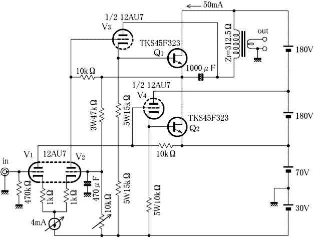
Tamura's PP transformer F-781 can be connected in parallel because two windings of 2.5 kΩ on the primary side are independently drawn out to the terminals, and when connected in parallel, the impedance becomes 1/4 of 625 ohms.
When 8Ω is loaded on the 16Ω terminal on the secondary side, the primary side becomes 312.5Ω, so I tried to draw a load line with this.


In the gate-drain voltage 450V at maximum rating of SIT, the gate-source voltage is generally a 20V, V D -I D towards the characteristic graph V D because it is documented = 600V, equivalent of a voltage It may be strong. 

However, since it is an expensive element, I will avoid using it unreasonably.
If the operating point is V D = 180V, I D = 50mA and the load line of 312.5Ω is drawn , V D = 13V, I D = 584mA, and the maximum output is 44.6W at V GS = 0V .

Gryphon Antileon Signature: Clone and Build

Get this from Walkalone from DIYaudio, a DIY hobbyist from VN.


The Basic Law of Gryphon's Design Topology

  • Non-GFB
  • Fully DC-Coupled
  • Class A output
  • Ultra-wide Bandwidth. 


The Gryphon Antileon Signature

Sansui Amplifiers 山水擴大機的歷史

不知為何,山水在國內外的鐵粉超多,有山水老資料庫,也有山水零件販售網,連二手拆下來的部件、PCB都賣,也很保值。相較於其他品牌,好像沒有一個品牌有那麼多人對"品牌"本身那麼瘋狂的,我的意思是,也許有人喜歡SONY某某機型、Pionner某某機型,但卻不像山水迷那樣,是對於這個品牌很執著信任,忠誠度非常高。

找了一些資料,根據已有的年份表再加以延伸
數個資料來源認為山水大約在1980~1990是黃金時期,1984年品質低谷,採用塑膠面板;後續90年代則力圖振作,但遇到日幣對美元升值、決策方向錯誤,也沒有新招可出,最後在2000年左右無力回天。


The History of Sansui Amplifiers.


韓國朋友來信: 有關JOB4修復

 The request of JOB4 repair. 

一位韓國朋友透過DIYA來信,說有一台JOB4想請我協助修復,據稱先前在韓國維修已經被搞得一團亂,有燒焦的電阻,維修完之後開聲沒多久就掛掉了。我建議他可以考慮Nuforce STA-200(因為根本就是JOB的複製),STA-200售價再高也不超過800USD,遠低於JOB4。但對方告知,這台機器對於他與他的父親都非常重要,有其特殊意義。恩...該怎麼辦呢?

我請他傳了幾張內部照片。JOB4的特點是把軸向電容都塞滿在PCB上面,所以其實我看不到維修的痕跡跟燒壞的電阻。從外觀來看,這就是典型的JOB、Goldmund機器,功率晶體採用巧妙的上下安裝,輸入採用A2之類的模組,電容用軸向電容,空間非常節省,設計精妙。不過說實在的STA-200打開也是這副樣子,已經修好幾次然後燒了一堆零件了,除了有特殊情感意義,不然真的沒必要再修了。

持續溝通中。


Hiraga Class A 20W


 終於有了兩聲道系統,尋尋覓覓,終於鎖定了這款簡單又好聽的後級擴大機線路---Hiraga 20W。原作者Jean Hiraga 於1980年代發表於L'Audiophile的線路,前後有好幾種版本,包含8W的Le Montre,30W,50W Class-AB等幾種版本。基於成本以及個人喜好,我決定挑選20W的版本來製作。以下是電路圖。

正負21伏特供電,八顆電晶體,就完成了基本放大線路,非常簡潔漂亮。


E-mu 0404 1212m 1616m 1820m PCI 音效卡 Windows11 驅動程式安裝 2025

E-mu 0404 1212m 1616m 1820m 音訊卡 驅動相容性與安裝 E-mu 0404 1212m 1820m等是歷久彌新的老音效卡,這些是Windows 7 時代製造且相對較老舊的音效卡。當時,AKM旭化成和 Burr-Brown 等廠商的 AD 轉換器都在爭奪板...