下面的方案僅僅針對SGD1和LA-QXD1來自SONCOZ的DAC,其他的機型僅僅只有參考的意義。
為了節約大家的時間,先說方法和結論:
調整ES9038Q2M DAC的IV轉換電路阻容配置以及LPF電路的阻容配置即可完全修復駝峰問題,屬於硬體修復方案!
To sum up, the "ESS Hump" of ES9038Q2M can be fixed by changing the setting of capacitors and resistors of LPF as well as I/V converter. The fixation is purely done by hardware adjustment.
驗證流程:
2019-12-10 13:30
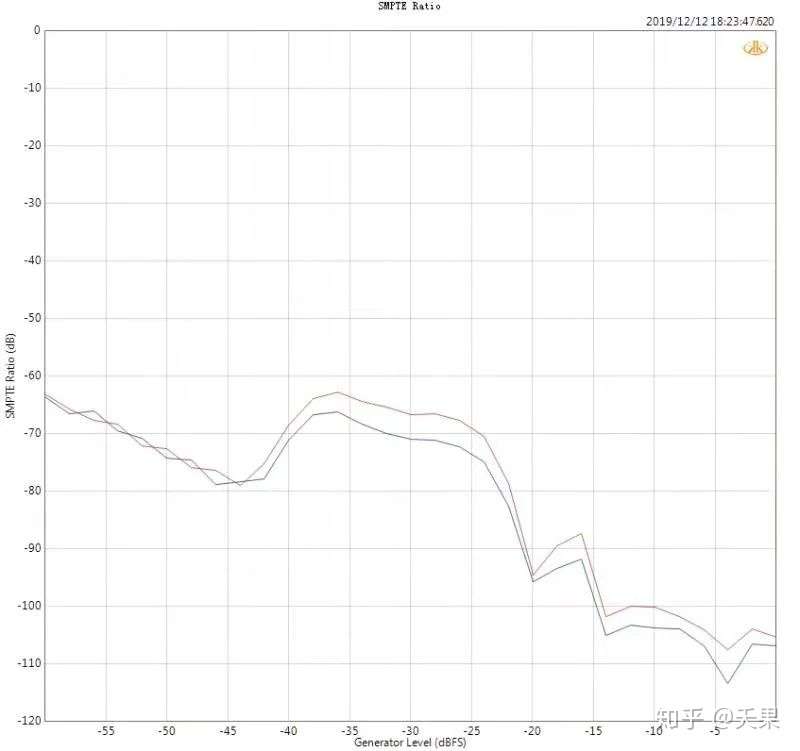
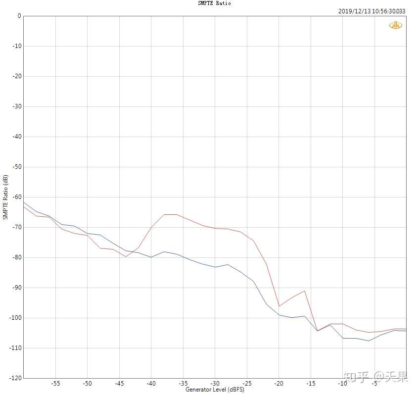
開始我的驗證和修復之旅。首先什麼也不做,看看駝峰的樣子,如圖:
First of all, the ESS hump shown without any fixation.
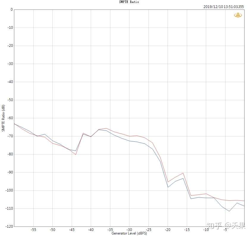
太醜了,我居然忽略了這個問題,請原諒設計過程不夠專業。藍色通道是我開始調整的通道,紅色通道是對比通道,便於區分。
我在設計中使用了兩種不同的運放。
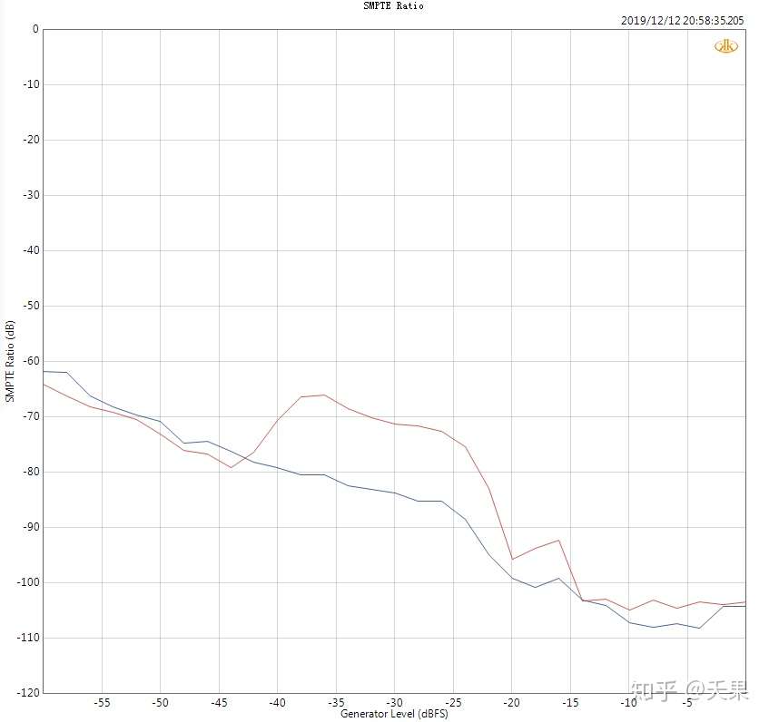
首先,我交換了(IV和LPF) 運放的位置。但不幸的是,駝峰仍然突出:
By using 2 different OPamps and changing their position (IV or LPF), there is no improvement of the hump.
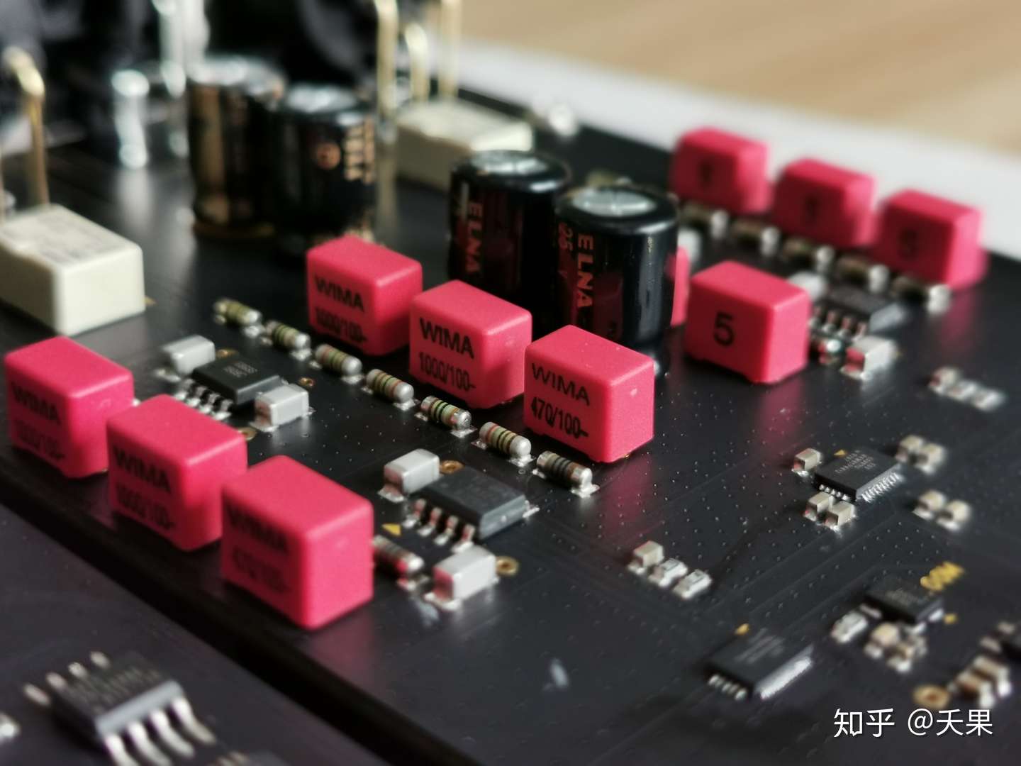
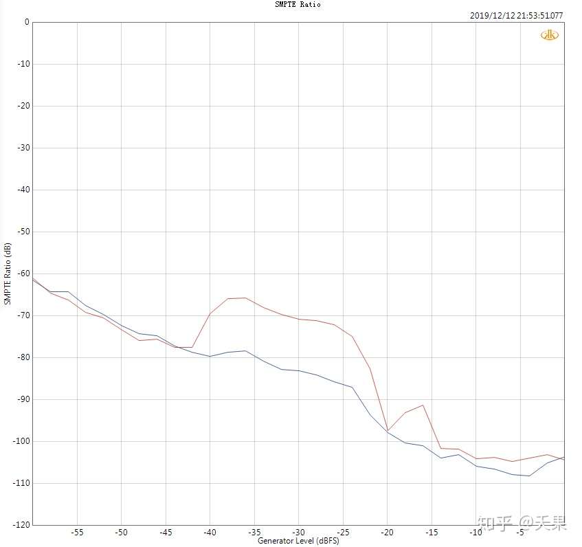
接著使用更高精度的電阻來驗證。在設計中使用的是百分之一精度的電阻,我早有準備。提前採購了多種千分之一精度的電阻:
Changing the 1% resistors to 0.1% in the circuit shows no or very little difference also.

依舊,駝峰變化非常不明顯,貌似不是電阻精度的問題,這時候有其他工作需要緊急處理,所以驗證工作稍微推後一些。
As a result, it seems the hump is not caused by the accuracy of resistors.
2019-12-12 16:20
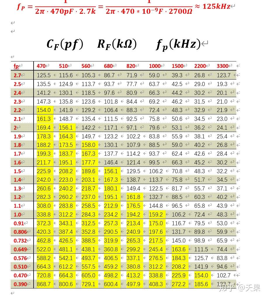
當我終於有時間繼續驗證時,我先做了一些計算,主要是IV部分的頻寬計算。正常來講頻寬越大帶來的干擾可能越多,所以在設計的時候只要能滿足音訊訊號的頻寬就覺得可以了,IV電路的設計頻寬大約在130kHz左右,在這個頻寬我得到了很好的其他參數,比如THD+N,線性度,訊雜比,串擾等。
我懷疑修改頻寬是否會改變我已經調好的參數,或者劣化我產品整體的效能,下面是我計算的手稿:
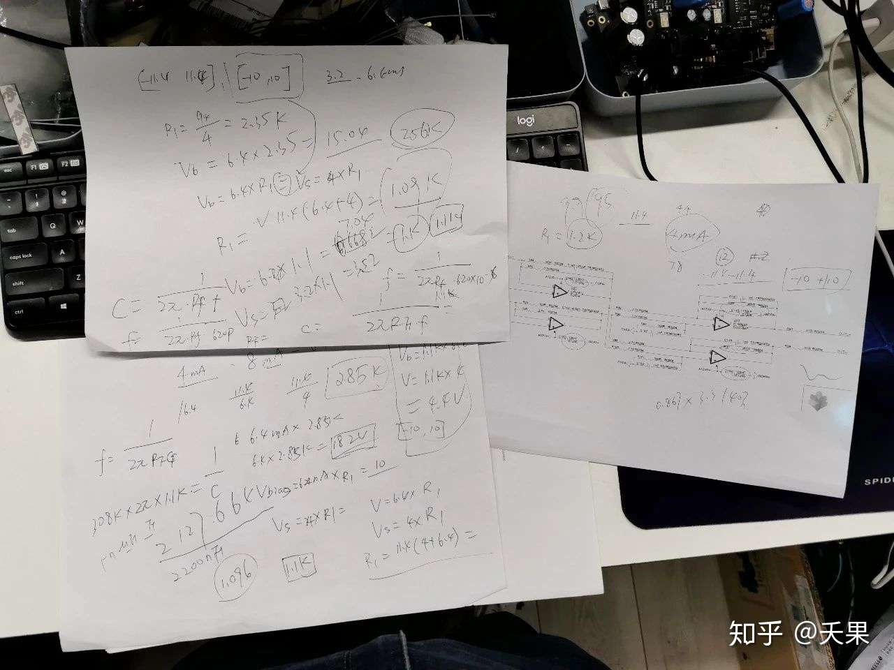
我在130kHzKz-500kHz範圍內計算很多種的IV阻容組合:
但最後驗證的結果卻啪啪打臉,駝峰依舊沒有明顯變化。
我決定要放過IV電路一會兒,試試調整LPF電路的電容,原始設計是1nF調整到2.2nF、3.3nF、4.7nF最後發現2.2nF的效果最好,如圖:
Let's forget I/V for a while, and try to modify the LPF's capacitors. The orignal design uses 1nF, and 2.2nF, 3.3nF, 4.7nF were tried and the result of 2.2nF is the best.
藍色通道確實有下降,但是這貌似就是下降的極限了,這距離平穩差距太大。
The blue line does decrease but it seems to be the lowest limit, which is not satisfying.

好吧,我覺得我餓了,需要補充點能量,吃晚飯去,順便清醒一下腦袋。
2019-12-12 20:00
晚飯回來繼續驗證,IV電路的頻寬是誰給我設定了最高500kHz的頻寬呢?為何不再高一點試試?我覺著這裡有鬼,我得馬上試試,我把IV的電容由470pF調整到100pF,出來了下面的結果:
The bandwidth of I/V is 500KHz; why not make it larger? So the 470pF was replaced by 100pF, and here is the result:
我於是在這樣的基礎上進行電容的調整,發現150pF的電容的效果優化的不錯:
Further adjustment shows the hump could be optimized by using 150pF capacitor in the I/V:
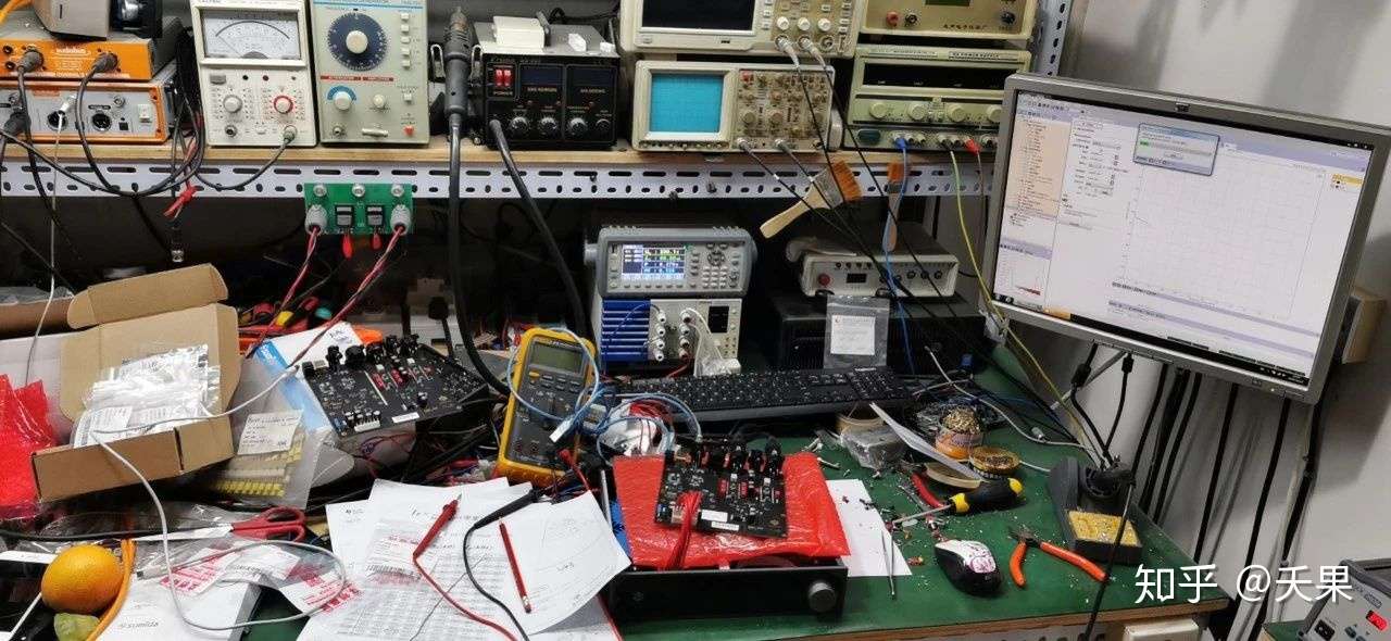
但是這個電容的數值不是一些常規的數值,在量產中可能會不好採購,但是現在我已經找到了方向。再看看我凌亂的實驗室,我覺得我需要睡一覺了:
2019-12-13 11:00
昨天晚上我讓機器一直工作,看看他的熱穩定性如何:
For better understanding of thermal stability, the DAC was kept on for a whole night; the result indicates the stability is good.
熱穩定性還不錯,沒有影響到駝峰,這是個好訊息。
按照昨天的思路和方向,在IV電路里面還有個電阻100R,這個參數應該也有調整的空間,先來試試調整到75R,如下圖:
Inspired by I/V capacitor, there is another 100R resistor in the I/V which can be modified as well. To beging with, 75R was used and shows:

他變得更平滑了,說明有效果,繼續驗證,調整39R,看圖:
The line becomes more smooth which means it works, so 39R was then used.
又更加平整順滑了一些,開心,繼續往下試試,51R,看圖:
2019-12-13 13:30
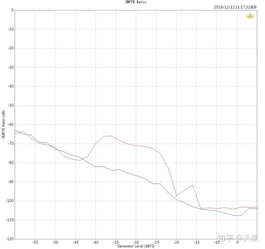
最後,經過幾次測試。電容值設定為220pF,電阻值設定為51R。我感覺這是我想要的結果,於是我兩個通道同時修改器件,調整輸出幅值,結果如下:
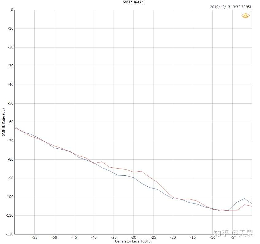
到此,我覺得駝峰的問題得以解決,忽略我手工焊接帶來的通道差異,不過這個駝峰確實很敏感,很難像幽靈一樣抓住它。電阻和電容參數的調整很小,駝峰變化很大。
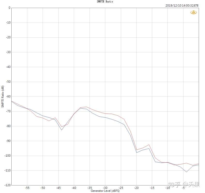
2019-12-13 14:00
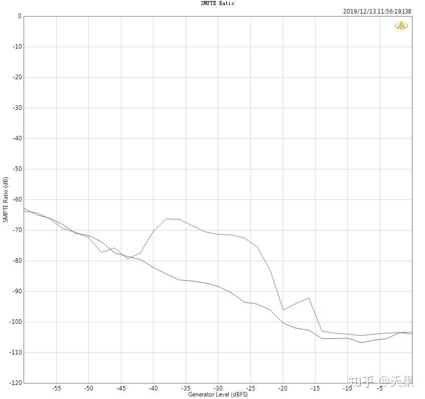
爲了驗證我的方案,我繼續在我小天鵝機器LA-QXD1上試驗該方法,同樣藍色通道是調整后的通道,看圖:
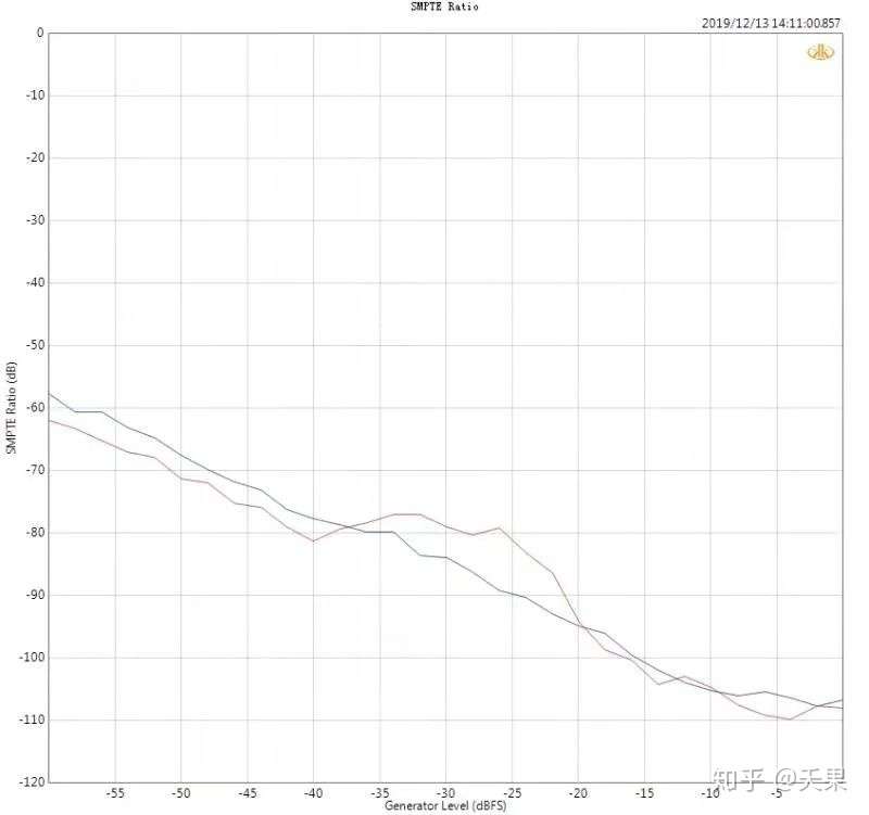
很神奇,一次性就很平整了,於是接著修改另個通道,紅色通道,看圖:
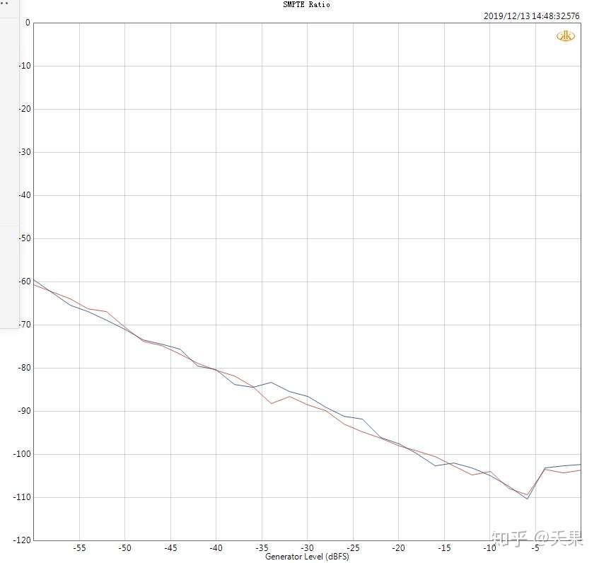
OK,我覺得方案是可行的,也驗證到這裡。
SGD1和LA-QXD1修正駝峰方法一致,所以這裡貼出SGD1的對比圖就可以。
當然,之前有人提到可以軟體修復,我僅僅嘗試過把Q2M的THN+N補償關掉和打開進行對比,結果沒有任何區別,我認為這是純粹的硬體bug。
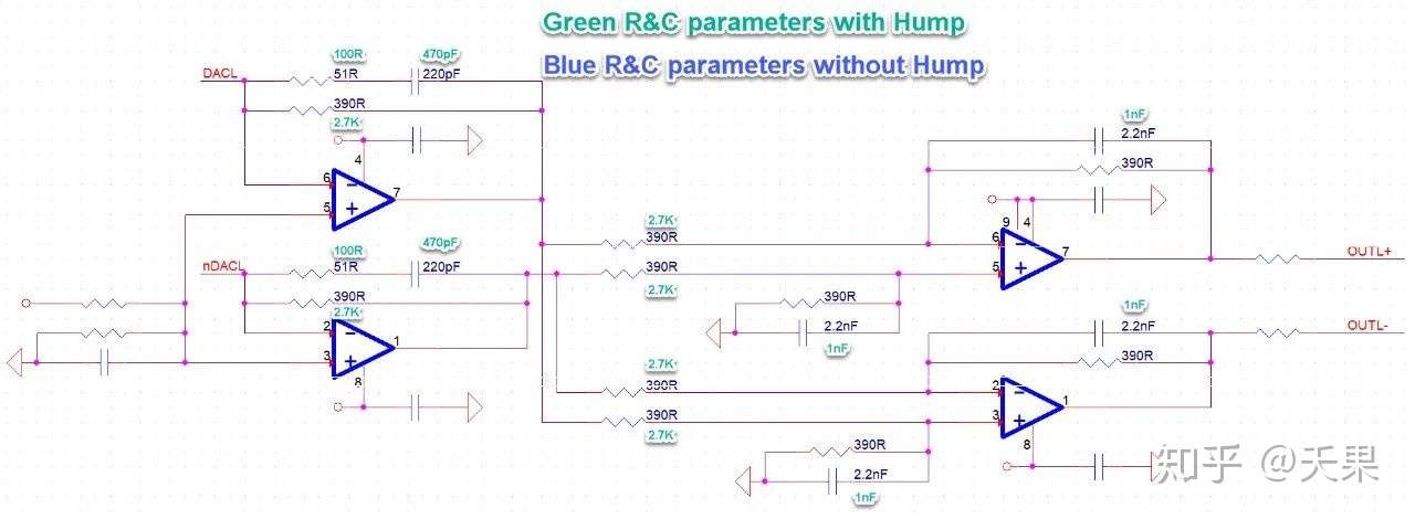
2019-12-22 09:00
最後貼出駝峰前後的電路,以作對比:
No comments:
Post a Comment